Part two of our comprehensive guide to building and piloting your own quadcopter.
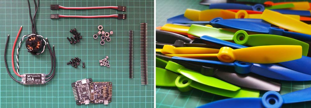
This tutorial covers the steps for building a DIY Quadcopter and is a continuation of the first part: Part 1. Read part 1 to understand how to choose the best parts for building a DIY quadcopter and how they all work.
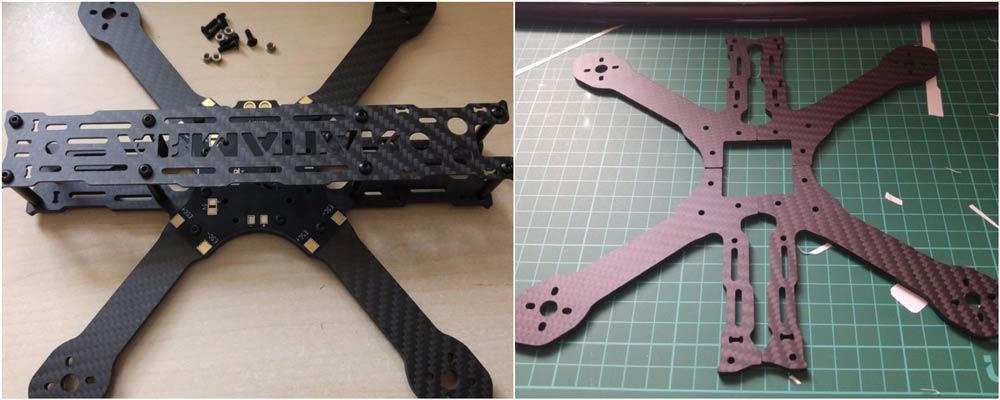
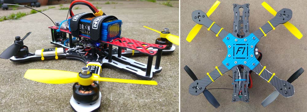
Assembling the Frame for the DIY Quadcopter
The first thing we need to do is assemble the frame. Most manufacturers provide an instruction manual, usually on their website. Follow the instructions and assemble the frame, ensuring that the flight controller mounting screws are in place. Once assembled, you can mount the flight controller. You can either do the soldering for the flight controller while it is mounted or you can do it before you mount it. I chose to solder while it is mounted as it keeps it firmly in place as I’m soldering.
Connect Voltage Regulator (if needed)
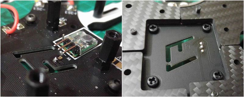
You can also connect the voltage regulator at this point. A voltage regulator is only needed when you are using ESCs that don’t have a BEC in them. I’m using ESCs that don’t have a BEC so I will need to use an external BEC or voltage regulator. My frame comes with an integrated Power Distribution Board (PDB) which has holes where you can solder the voltage regulator. Yours may not. If it doesn’t, you can simply connect the VIN and GND to one of the spare positive/negative pads on your power distribution board. I will show you how I connected mine to the PDB on my DIY quadcopter.
The Pololu 5V step down or buck regulator is pretty common and is very straight forward. The Pololu comes with a pin header that has 4 pins. We only need three pins, so break one off so that you have 3 pins. Solder the pin header into the VOUT, GND, and VIN. Once soldered, you need to bridge the SHDN pin to the VIN pin. This makes the output current 600mA. If it wasn’t bridged, then the output current will only be 20mA, which isn’t enough to power the electronics. I did it by soldering a pin taken from a pin header to bridge the two. A simpler method is to bridge them with just solder. Once bridged, connect the VIN and GND to any spare +/- pads on the PDB. The VOUT and GND connect to any power pins on the flight controller. Once it is connected to the flight controller, you can then power your other electronics from it, such as the LEDs and the receiver.
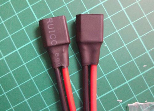
Now we have to solder together an XT60 connector. Creating the XT60 connector is very simple. All you do is solder a red wire of the correct gauge to the positive terminal and a black wire of the same gauge to the negative terminal and then place heat shrink over each wire at the solder joint. You can watch this video to learn more about how to create the XT60 connector or you can simply buy one. Grab some spares too for your DIY quadcopter.
Preparing the Quadcopter Flight Controller
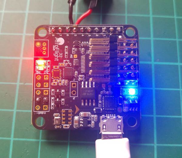
Test It: Before you solder onto the flight controller, test that it works by plugging it into the computer using a micro USB cable. If all the correct LEDs light up and it has connected successfully, you can then disconnect it and move onto the soldering.
Flash It: It's a good idea to flash your board beforehand. To do this, jump the boot pads on the board and then connect it to the computer and launch CleanFlight. Go to 'Firmware Flasher' tab on the left, enable 'No reboot sequence' and choose the correct firmware from the drop down menu. Once it has loaded, click on 'Flash Firmware'. Once the board is successfully flashed, disconnect it from the computer and remove the solder from the boot pads. Watch this video to learn more.
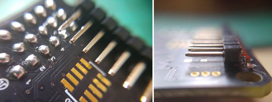
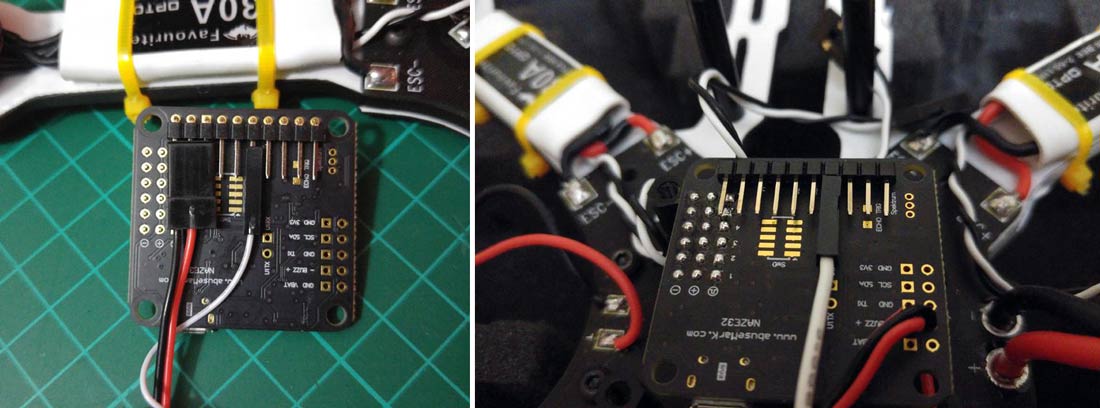
Solder It: The Naze32 comes with a set of pins. Solder the pins to their corresponding holes. You can solder them in any way you like. I chose to go for a low profile build and I soldered the breakout cable pins beneath the board. Make sure you solder the pins right the first time. Dry test the pin placement or configuration first and once you've found a placement/configuration which you like, proceed to the soldering. Trying to desolder the pins is exceptionally irritating. Once you've removed the set of pins, it's virtually impossible to get them back in even after you've removed the solder from the holes because the pins fit perfectly and there's no wiggle room. Albeit I was using a solder vacuum pump to remove the solder. You'll probably find better results if you use a desoldering station to completely remove all solder from the holes.
Prepping the Motors for the Quadcopter
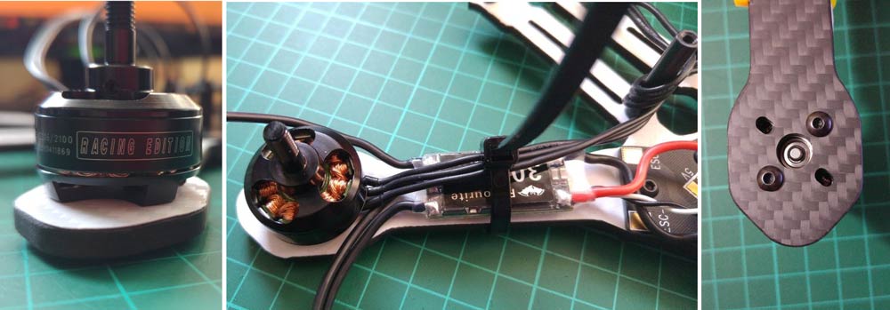
Mount the Motors: In order to know how long we want the motor wires, we need to first mount a motor to the boom. This can be done by using the screws provided with the frame or the screws provided with the motors themselves. What we’re going to do is use one motor and one ESC to get the right length and then use that length to cut the wires of the other three motors, this way, we can save some time since we don’t have to repeat the process for all 4 motors of your DIY quadcopter.
There are 4 mounting holes for the motors. For this stage, you don’t need to put in all 4 screws so you can use 2 and make sure that they are opposite each other so that it fits correctly. When you're done, you can add the other two screws or even stick with two. Some pilots such as FinalGlideAus have reported that they've had no trouble using only two screws. The key is to make sure that they are all of the correct tightness.
Measuring and cutting the motor wires: The wires that come out of the motor can be quite long so we need to measure them and cut them. Start by zip tying the ESC to one of the booms. At this stage, it doesn’t matter which boom, any will do. Now you can adjust the position of the ESC along the boom to see how you want it to fit.
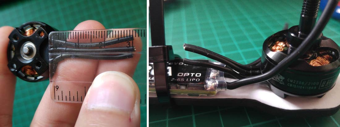
Once you have it where you like, cut the motor wires ensuring that there is enough length to reach the solder pads. Now you can remove the motor from the frame and measure its length. Once you have your length, cut the wires of the other 3 motors to the same size.
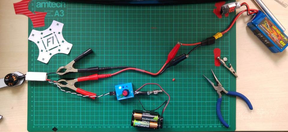
Testing the Motor Direction on Your DIY Quadcopter
Once you have stripped the motor wires back you can then test the motor direction. You need
two spinning clockwise and
two spinning anti-clockwise motors. You can do this with a
servo tester or through
CleanFlight. I will show you how to test with a servo tester.
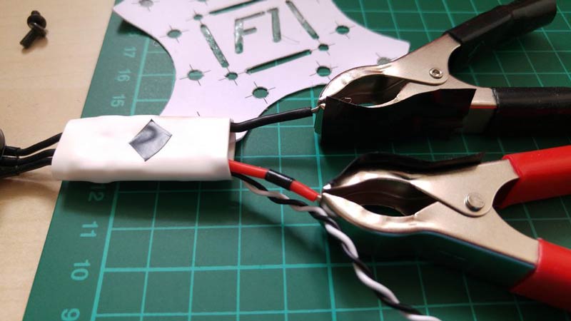
Use crocodile clips to connect together the motor wires from the ESC and motor. Use some more crocodile clips to connect the battery to the ESC using the XT60 lead soldered earlier.
Connect the signal lead from the ESC to the'OUT' pins of the servo tester. Connect the power supply to the servo tester through the 'IN' pins with a 3 or 4 AA battery holder. Plug in the LiPo battery and then slowly turn the potentiometer until it spins. Observe the direction that it spins in and take a note of it. Repeat for all motors and ESCs making sure you know which motor is spinning in which direction. To reverse the motor direction, you can do so by simply switching any two of the motor wires.
STEP 5: Soldering Motors to ESCs
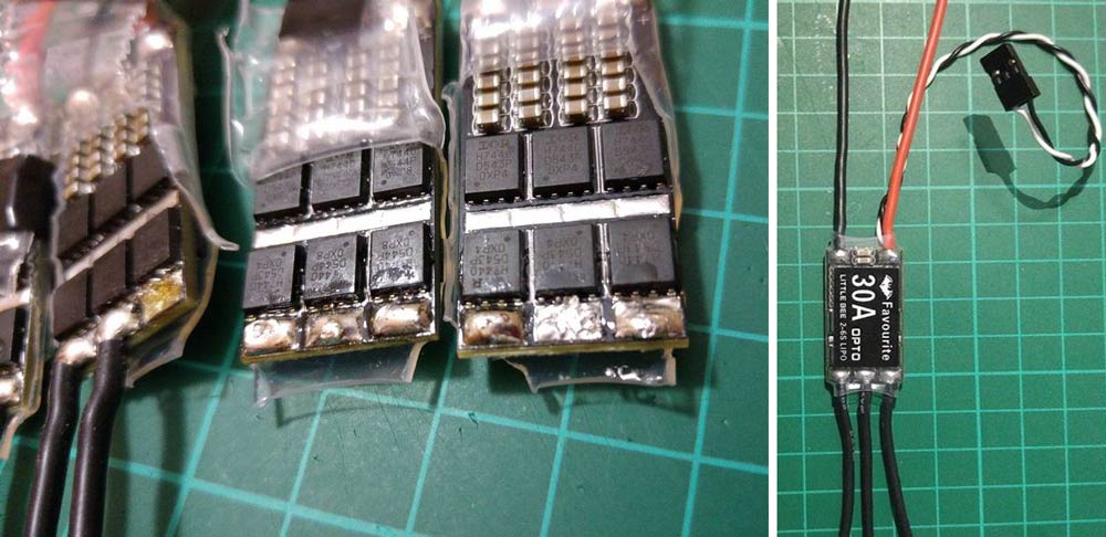
Desolder the ESC wires: There are a total of 7 wires soldered to the ESC. The three on the right connect to the motors, and on the left, the red and black are for the power. The twisted black and white wires are for the signal. In order to have a cleaner build, you want to remove the 3 motor wires on the right and solder the wires from the motor itself directly to the ESC. This saves weight and makes it look nice and neat. You want to repeat this step on all ESCs. Remove the heat shrink before soldering to expose the solder joints.
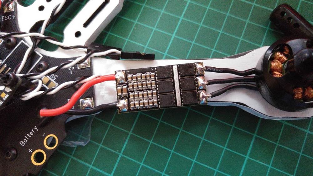
Solder motors directly to ESC: Now that the three motor wires have been desoldered, the ESCs are now ready to be soldered on to. First, strip the ends of the wires. Then tin the ends of the wires by applying a small amount of solder onto them. Tinning just means to apply solder onto the joint beforehand so when you want to solder them together, the solder is already on there and you won’t have to grow a third hand just to hold the solder. Tin the ESC pads also, if not already.
Once the wires and pads are both tinned, you are ready to solder the wires to the pads. Place the wires on top of the pads and apply heat using the soldering iron until the wire melts into the pad. Repeat for each wire until all motors and ESCs are connected on your quadcopter.
Once all motors have been soldered to the ESCs, proceed to mount the motors to the frame using the screws provided. Make sure that the screws you’re using aren’t too long. Long screws can poke into the windings of the motor, resulting in damage. Check the length by peeping through the gap at the bottom of the motor and see if you can see any screws poking into the windings.
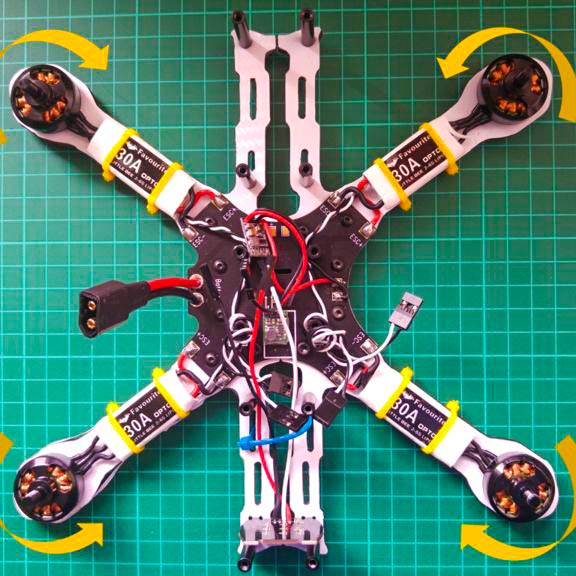
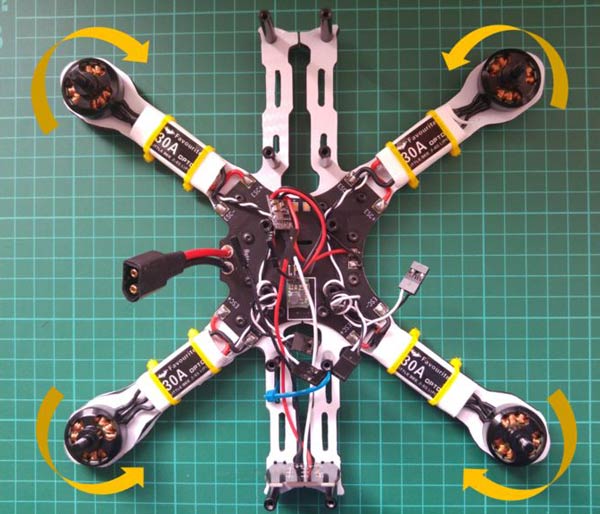
Motor Placement: Be wary of the placement of the motors of your DIY quadcopter. You have two spinning clockwise and two spinning counter-clockwise motors. The picture below shows where each motor should be placed and the direction it should be spinning:
Top left = Clockwise
Top right = Counter-Clockwise
Bottom right = Clockwise
Bottom left = Counter-Clockwise
A way to remember this is that all motors spin inwards towards the center. If you look at the picture above, you can see that the arrows point to the center along the y-axis. When mounting the motors, make sure that the quadcopter frame is facing forward and double check that the motors are in the correct places before moving onto the next step.
The reason for this is to do with torque. Each motor produces torque in the opposite direction that the propeller spins in. If we had all motors spinning in the same direction, the quadcopter would spin as fast as the motors (in theory) making the yaw axis uncontrollable. To counteract this, we have two spinning clockwise and two spinning counter-clockwise. This cancels out the torque of the other motors, allowing for stable flight. It's the equivalent of what a tail rotor does in a helicopter.
Soldering the ESCs to PDB
Before you solder the ESCs to the PDB (Power Distribution Board), put the heat shrink tubing over the ESC but don’t apply the heat yet. You may need to swap some of the wires later and you won’t be able to with the heat shrink in the way. Some ESCs allow you to reverse the direction without having to resolder any wires. The KISS ESCs have jumper pads where if you bridge them, the motor spins in the other direction. On the Littlebee ESCs, you can change the motor direction through BLHeli which is a software used to program it.
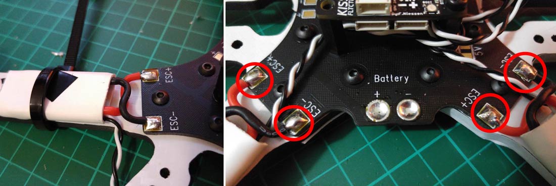
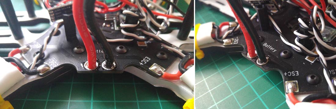
First, tin the wires and the pads and apply heat to both of them until the wire melts into the solder on the pad. Make sure that positive (red wire) goes to positive and negative (black wire) goes to negative. Do this for all 4 ESCs. You can use double sided sticky tape beneath the ESC to dampen any vibrations. Once you have shrunk the heat shrink, secure the ESCs to the frame using zip ties or even insulation tape, although zip ties would look neater on your DIY quadcopter.
Solder XT60 to PDB: Take the XT60 connector you made earlier and connect it to the PDB. The red wire goes to positive and the black wire goes to negative. Double, triple check that you have the correct polarity otherwise things can go south very quickly.
Adding Accessories: Buzzers and LEDs
You can add LEDs strips and buzzers to your DIY quadcopter to make it even more awesome. The LEDs help with orientation and the buzzers are useful for when you crash and can’t find your quad. You can flip a switch and the buzzer will beep, making it easier for you to find.
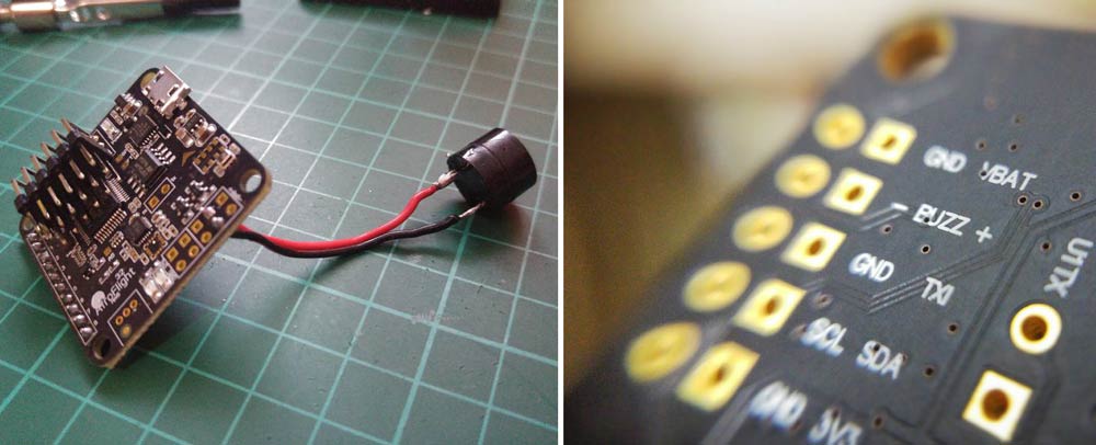
Adding the buzzer: Some flight controllers have holes specifically for the buzzer. To add the buzzer, simply solder the positive wire to the positive hole on the flight controller and the negative wire to the negative hole. Double check that the polarity is correct so positive is going to positive and negative is going to negative.
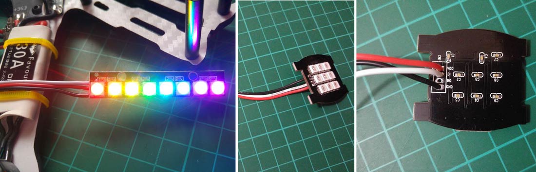
Adding LEDs: To add the LEDs, solder a servo lead onto the LED solder pads. DI is the signal or data in connection, VIN is positive and GND is negative. DO is the data out connection. This is only needed if you are daisy chaining multiple LEDs. To daisy chain multiple LEDs, connect DO of the first LED to DI of the second LED and repeat for any additional LEDs, connecting the DI of the previous to the DO of the next. Once soldered, connect the positive and negative servo lead to the spare ESC pins (5 or 6) and connect the data lead to pin 5 (LED/5) on the Naze.
Connecting the Wires and Battery
Connecting the wires: Once all the soldering is complete, the wires need to be connected. The following are all the wires on your DIY quadcopter that need to be connected:
4 signal/ground wires that come from all 4 ESCs
1 power wires (Red+Black) from the voltage regulator
3 wires (Red+Black+White) from the receiver
3 wires (Red+Black+White) from the LED
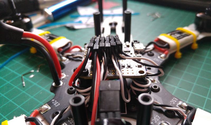
Connect the 4 signal/ground wires from the ESCs to the ESC pins on the Naze32. Make sure that it is the right way round and that pin set 1 is connected to motor 1. Each flight controller has different orders of the motors. Check the photos above for the order for the Naze32. On the bottom of the board, you can see which set of pins are for motor one and so on.
The last two sets of pins (5&6) are the spare ESC pins which we can use to connect the accessories. Connect the voltage regulator wires to one of the spare pins. Make sure that it is the right way round. For the LED, the red and black wire go to the second set of spare pins and the data wire (white) connects to the ‘LED/5’ pin. Make sure that it is the right way round.
Now all the soldering and building is complete. Next, you need to set everything up by performing calibrations and configuring the settings. This will be included in Part 3 of this guide which will focus on the software side and expands on learning how to fly. It will include: how to calibrate the ESCs, how to setup the flight controller and transmitter while covering topics such as failsafe, what to do if you lose your quadcopter and more. Part 3 coming soon.
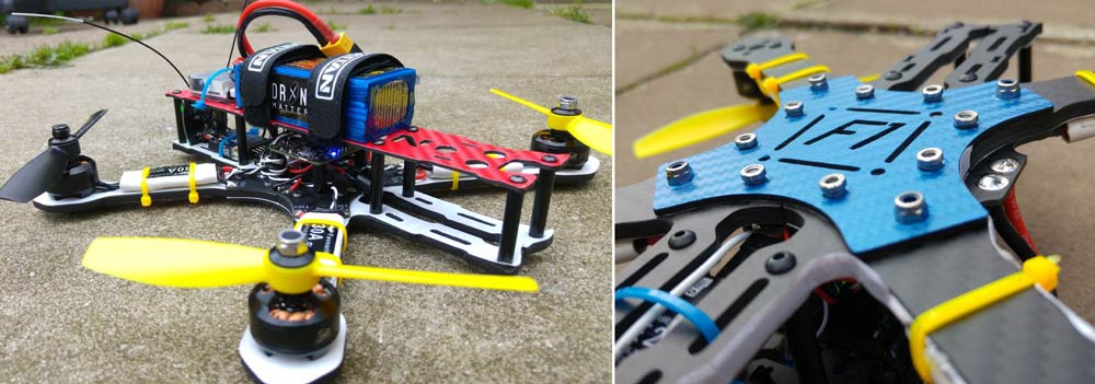
Connecting the Battery: The battery usually sits on top of the frame, at least for FPV quadcopters. Onacro quadcopters, they usually sit on the bottom of the frame due to the design and allocation of components.
Center of Gravity: Your Centre of Gravity (CG) should always be in the middle of your DIY quadcopter. If you're adding FPV, you will have extra weight at the front so you're usually going to have to compensate by moving the battery backward a little. If you don't have FPV, place it dead center.
Connecting the Battery for the First Time: Use the XT60 connector that you soldered to the PDB to connect it to the XT60 connector attached to the battery. The XT60 is keyed so it can only go in one way. But before you connect it, use the smoke stopper mentioned earlier to diagnose any faults before blowing any components. Once you connect it, you should hear 5 beeps coming from the motors/ESCs. This depends on the ESC itself but most ESC's I have heard 5 beeps. The first three beeps confirm that the ESC has turned on and the last two beeps confirm that there is a successful connection to the flight controller. If you only hear three beeps when you should be hearing five, double check the connections between the ESC and flight controller. Check that they are connected the right way.
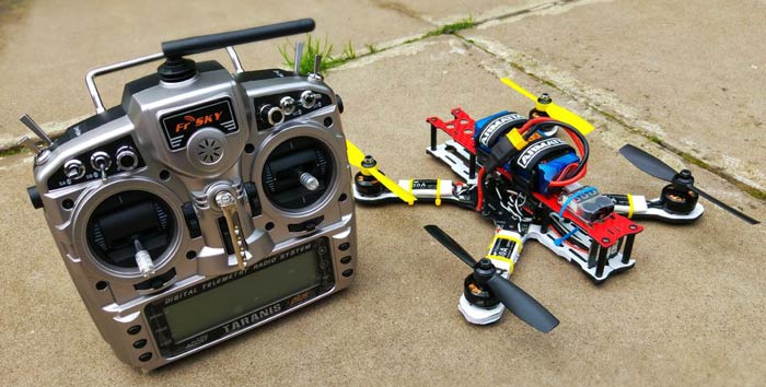
And that's it, you have just completed the build for your DIY quadcopter!
This is the demo flight video for my DIY quadcopter.
Maintenance and Repairs for Your DIY Quadcopter
Buy Spares: It is wise to buy at least one spare for each component. If you can't buy at least one spare for each, then just get a spare ESC and motor. The other components are less likely to fail/break but it's useful to have a spare lying around. The most important ones are the ESCs and the motors. The ESCs are the most likely to be the first ones to go. The motors are more resilient but sometimes you get a dud and have to get a replacement. Also, buy extra propellers. Lots of them!
Buying spares is useful because it saves time and money as you don’t have to wait for the components to arrive and don’t have to go through the pain of shipping and customs charges all over again. This way, when you have a bad crash and your motor shaft bends, you can get back to flying within the day or even the hour.
Buy Multiple Batteries: You will find that you need quite a few more than just one battery. Flight times for racing quadcopters are typically around 4-8mins which isn't a very long time. Waiting one hour for your battery to charge, flying for 5 minutes and then waiting another hour for it to charge is just inefficient and not to mention annoying. The problem is, batteries can be expensive, especially if you're buying multiple. If you have at least two or three, it'll give you a little more time to fly before having to recharge. Some people even carry more than 30 batteries! Which allows them to fly for the whole day without having to even worry about charging.
Repairing: If you have a bad crash or one of your components spontaneously commits suicide, you can easily fix the problem with a soldering iron. Simply repeat the steps you took to install that particular component and replace it with a new one. For example, one of your ESCs gets burnt out. You would desolder it and solder in a new one. You would then flash it, calibrate it and test it to see if it's working properly.
Health, Safety and Drone Law
The Law: There are certain things you must consider when pursuing this hobby. Remember, these are not toys and they must be treated with respect. We live in a time where the general public fears drones and the government has made flying them quite strict. Careless UAV (Unmanned Aerial Vehicle) owners unknowingly make silly mistakes and end up injuring someone or damaging property or flying it too high and interfering with airliners, forcing the government to enforce stricter laws which makes it harder for the responsible people who love this hobby to fly their quadcopters.
It’s important to know the laws in your area regarding the flying of quadcopters. In many countries, you cannot fly above 400 feet, or fly in the near proximity of airports and airfields. If the DIY quadcopter is fitted with a camera, it must not be flown within 50m of any buildings, people, or large gatherings of people such as a stadium. It’s best to fly in the morning in a large open field where there will be hardly any people around and where there is no risk of injury/damage occurring to people or property. Here is a CAA article on the laws regarding UAVs in the United Kingdom.
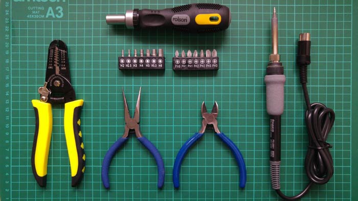
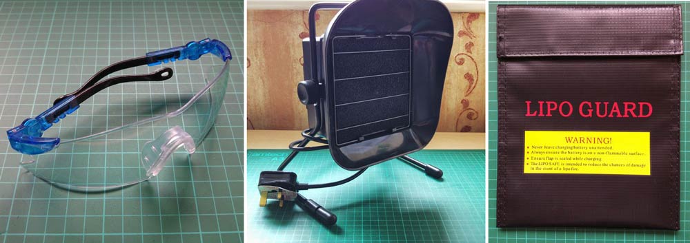
Health & Safety: During soldering, ensure that you have some form of fume extraction. Even a gentle fan blowing the harmful fumes away from your face can make a big difference. It is best to buy a desktop fume extractor or build one. It’s nice and small and is cheap to buy/build.
Always wear safety goggles when soldering. Solder can spit and may one day spit into your eye, causing permanent eye damage. This can be prevented by simply wearing safety goggles.
When charging your batteries, always charge them in a fire-safe bag. If it bursts into flames, the bag will contain the flames and reduce the chances of fire spread. But this is not a bulletproof method. It reduces flames, it doesn't eliminate them so don't rely on this method. Charge outdoors, away from any combustible materials. Here is a video from FliteTest about a useful battery bunker you can make to safely charge your batteries outside.
Learning to Fly
Just like a full-size aircraft, one must first learn how to fly. It may seem easy, but you’ll be surprised while flying your DIY quadcopter.
Practice on Something Smaller First: It’s not a matter of if you crash, it’s a matter of when. So to prevent damage to your expensive quadcopter, it is highly recommended that you build or buy a cheap ‘sacrificial’ quadcopter. This way, when you crash, you won’t have to worry about replacing expensive components and you can fly without the fear of breaking anything. It’s best to start with the small and fairly harmless micro quadcopters such as the Hubsan X4. These micro quadcopters are very cheap and are surprisingly durable. Once you have mastered the basic flying techniques on the micro quadcopter you can move onto your larger, more powerful quadcopter.
Learn from YouTube: To learn the basic flying techniques, I recommend watching this excellent video series created by Jack FPV. He goes into good detail and provides drills and exercises that you can use to practice such as fixed position hovering and flying in patterns. FliteTest also has a great video which really helped me understand how to fly quadcopters when I was learning.
Flight Simulators: Flight simulators are an excellent way to learn how to fly without the risk of damaging anything. You can fully let go and fly without fear of crashing. FPV Freerider and Liftoff are great platforms for learning and are inexpensive. Buy your transmitter first so that while you're looking for the other components, you can connect it to your computer, learn how to fly, and master it before you've even built your DIY quadcopter.
The video above is me flying on the FPV Freerider flight simulator. I connected my Taranis to the computer and used that to control my DIY quadcopter. If it's raining outside or if the weather isn't permitting, flight simulators is a good way fulfill your needs.
I hope you enjoyed this diy quadcopter guide and I wish you good luck on your build. Part 3 is coming out soon and will include the software; how to configure and set everything up to get your quadcopter up in the air. Until then, I bid you farewell. Be sure to share your thoughts in the comments below. Happy Flying!