This series will give you all the required information to build or tweak a mechanical narrow band television.
Editor’s Note: This is part of a several part project by Vincent Portet. If you would like to see a specific chapter, refer to the table of contents below.
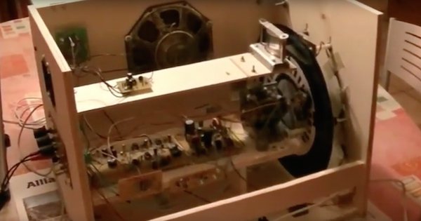
This series will give all the required information to build or tweak a mechanical narrow band television similar to the prototype shown in this Youtube video. In part 1, we will focus on some of the core concepts. Later, we will get into building our own color mechanical TV!
Building and tweaking this kind of mechanical and electronic hardware requires some experience and a lot of patience. Electromechanical parts (speed response vs torque of the available motor, disc inertia, and size) have an impact on the global system behavior so the prototype will not be “plug-and-play”. A lot of adjustment means have been implemented in the schematics to face these kinds of issues. However, it remains possible that you will have to modify some values/components to match with your mechanical configuration, especially in the motor synchronization system (as in all other kinds of mechanical TV designs). If experienced in homebrew design but not familiar at all with NBTV and/or mechanical television, I recommend checking out the Early Television Museum website.
The design proposed in this document is modular so that it is possible to choose some parts from it, if not all of them, according to one's preferences:
- Video synchronization extractor + Y / green extractor
- Motor driving system disc synchronization with video
- Vsync triggered stroboscope for an easy adjustment of vertical synchronization by the user.
- Low loss LED anode voltage regulator (avoids thermal dissipation issues and reduces power consumption), made with very common components.
- SECAM-like color decoder + audio separator, if willing to build a color TV (includes a PIC1F819).
No particular design is proposed for the audio amplifier since any kind of audio amplifier (
having an input impedance higher than 10K in the case of a color system) can match for this purpose. For the prototype shown in the video, I simply used a small IC demo kit that I had saved from the trash at my workplace as an audio amplifier.
Input Signal and Main Features
Like many other NBTV systems, this proposed piece of hardware handles a narrow band video signal stored in a specifically generated computer file. The file type is WAV, commonly used for audio recordings: A classical lossless 2-channel (stereo) recording file at 48000 spl/s. Therefore it makes sense to talk about pixels like in digital video because the video signal sampling rate directly gives the number of produced pixels per second when scanning a line (even if you plan to reproduce this signal later with some custom analog equipment).
Black and White Mechanical TV System
The first channel is used for composite monochrome video (Vsync/Hsync/Lum). The second channel is used exclusively for audio.
In this case, where you don’t use the color decoder, you will at least have to insert this filter between the computer audio channel output and the audio amplifier input to suppress the color carrier superimposed by default by the software converter. (If the amplifier has no volume control, insert a 10K potentiometer - as a voltage divider - between the filter output and the amplifier input)
Color Mechanical TV System
- The first channel is used for composite green video (Vsync/Hsync/Green)
- The second channel is used for low-pass filtered audio + SECAM-like color carrier (alternatively providing the blue and the red color signals. No YUV optimization is handled at this time).
Mechanical Rasterizer, Resolution, and Size
The mechanical scanning system is based on a Nipkow disc. However, the electronics could be used to drive other mechanisms (drums, mirror screws...). But we will assume for paper simplification that a Nipkow’s disc is used.
Experimenters willing to build their own Nipkow’s disc can use this helping SW tool.
http://users.tpg.com.au/users/gmillard/nbtv/DXFNipkow.zip
The electronics and the video generation software tools are designed to be compatible with 30-line and 60-line discs while reserving the first line for a HSYNC signal. In other words, the first line sector is present on the disc (and the corresponding hole can exist) but is it always black, bringing the effective resolutions at 29 and 59 lines. The rasterization is horizontal like in classical video (unless the original video has already been rotated before creating the NBTV video), and its speed is 12.5 frames per second.
The prototype shown in the Youtube video is based on a Nipkow’s disc spinning at 12.5 turns per second. It is relatively small, especially if dealing with 60 lines. This experience helped to conclude that such a small disc featuring so many lines can only be built with advanced machining equipment. Even a printed template and a careful driller will not succeed in reaching a satisfying result. This is why generated pictures shown in the video are disappointing. Handmade discs should be 30-line discs with a diameter close to what can be seen in the video (27 cm) or 60-line discs, two times bigger if targeting an aspect ratio close to 1:1 and a reasonable picture size.
Aspect Ratio Considerations
The goal of building such a small disc was to optimize the ratio [Picture width] / [Disc diameter] by creating shrunk pictures on the disc which could be horizontally extended with the help of an anamorphic lens. However, this prototype particularity is just an example and all the stuff presented here can be used with more classical Nipkow’s discs, provided that some care is taken for the aspect ratio:
The original video file to be processed by supplied software (detailed further) must have the same aspect ratio than the final picture to be created on the disc (directly depending on disc geometry). The video converting program will adapt the entire original images to fit in an NBTV video at 57x59 pixels or 121x29 pixels for 30-line variant. In other words, pixels may not be "squares" depending on what you do: With 60 lines, the effective pixel shape proportions are almost the same than the disc-created picture proportions, while with 30 lines, the ratio height/width is quadruple. (Pixels are in fact more similar to small bars perpendicular to lines, like in the most current cases of 30-line television systems. Ideally, the disc holes should have the same proportions and shapes but this is not possible).
In the next installment, we'll talk about the components used to make it and design some circuits! If you want to check out another mechanical TV design, be sure to look at Robin Mitchell's Baird Mechanical Television tutorial!