This project describes how to create the electronic components for a simple basketball
arcade machine using an SLG46537.
Below we described steps needed to understand how the solution has been programmed to create the basketball arcade machine. However, if you just want to get the result of programming, download GreenPAK™ Designer software to view the already completed GreenPAK Design File. Plug the GreenPAK Development Kit to your computer and hit the program to design the device.
In this project, a pair of Dialog GreenPAK SLG46537’s is used to create the electronic components for a simple basketball arcade machine. These machines tally baskets scored within a certain amount of time. They can often be found in arcades like Chuck E. Cheese’s or Dave & Buster’s.
Basketball arcade machines exist in both free-to-play and pay-to-play varieties, and may or may not dispense tickets based on the number of baskets scored. We will ignore these extra options, and focus on the main elements that the machine should have.
Core Hardware
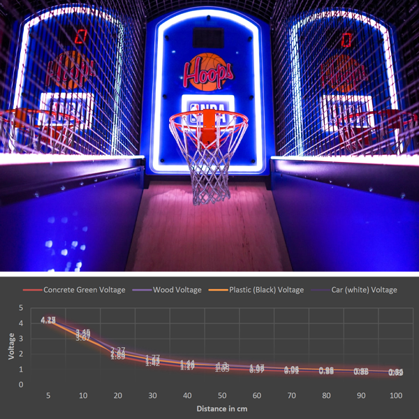
The core function of the system is sensing the ball going through the basket, so we need a proximity sensor well suited for small distances. A good pick for this job is the GP2Y0A60SZLF analog distance sensor, which has low power consumption and has been used with other GreenPAK projects.
We are also going to need a display. Knowing that the intended use is for entertainment, and having a budget in mind, we selected two 7-segment displays of 6.5 inches in size. These parts are a couple of YSD-1100AR7B-15 units from SparkFun electronics.
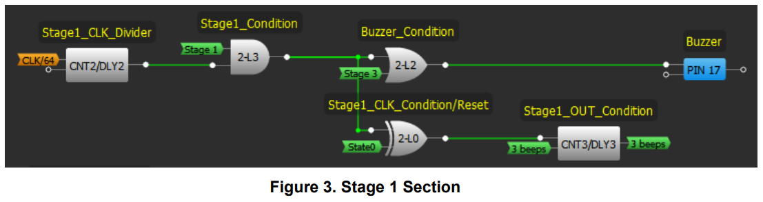
The YSD-1100AR7B-15 parts need a minimum voltage of 12 V to work, so driving them directly with a GreenPAK is not a good idea. Instead, we are going to drive the displays using two CD4026 ICs, which are used for driving 7-segment LED displays with voltages up to 18 V.
We are also going to need a buzzer to emit the sounds of the game. Luckily, a simple 5 V buzzer is sufficient for this application, as most of them have decent volume.
Finally, to help the TTL signals from the GreenPAK drive the CMOS inputs of the CD4026 ICs, we need to drive the 12 V supply of the ICs.
An excellent way to shift the voltage levels is using a MOSFET and a Pull-UP resistor like in Schematic 1. (A PDF of it is included).
State Transitions
The arcade machine should be able to adhere to the following routine:
● State 0 - The arcade is powered on and the score display shows the last game’s score.
● State 1 - The start button is pressed, the score display is cleared, and beeping signals the start of the game.
● State 2 - This is the main game stage. It should last 60 seconds, receiving the signals that a ball has fallen inside the basket.
● State 3 - A loud beep signals game over and the score flashes before settling in a continuous fashion.
● State 0 - Repeat.
This main routine has the core functionalities of a basketball arcade machine focused on personal use.
Main Routine
In this section, we are going to specify what kind of processes are going on in each of the stages.
Stage 0
The asynchronous state machine (ASM) is in state 0 waiting for the start button to be pressed, after which it will move onto stage 1.
Stage 1
The start button was pressed and now the system is in stage 1. The system is going to emit a beep 3 times, signaling the start of the game and moving the system into stage 2. Also, it’s going to reset the score shown on the display.
Stage 2
Stage 2 is going to be activated for exactly 60 seconds. During these 60 seconds, the output of the system will be signaling a CD4026 with the number of times the ball passed through the basket.
Stage 3
After 60 seconds have passed, the system moves onto stage 3. A loud beep and the flashing lights of the display are going to signal game over, after which we reset into stage 0.
GreenPAK Main Routine
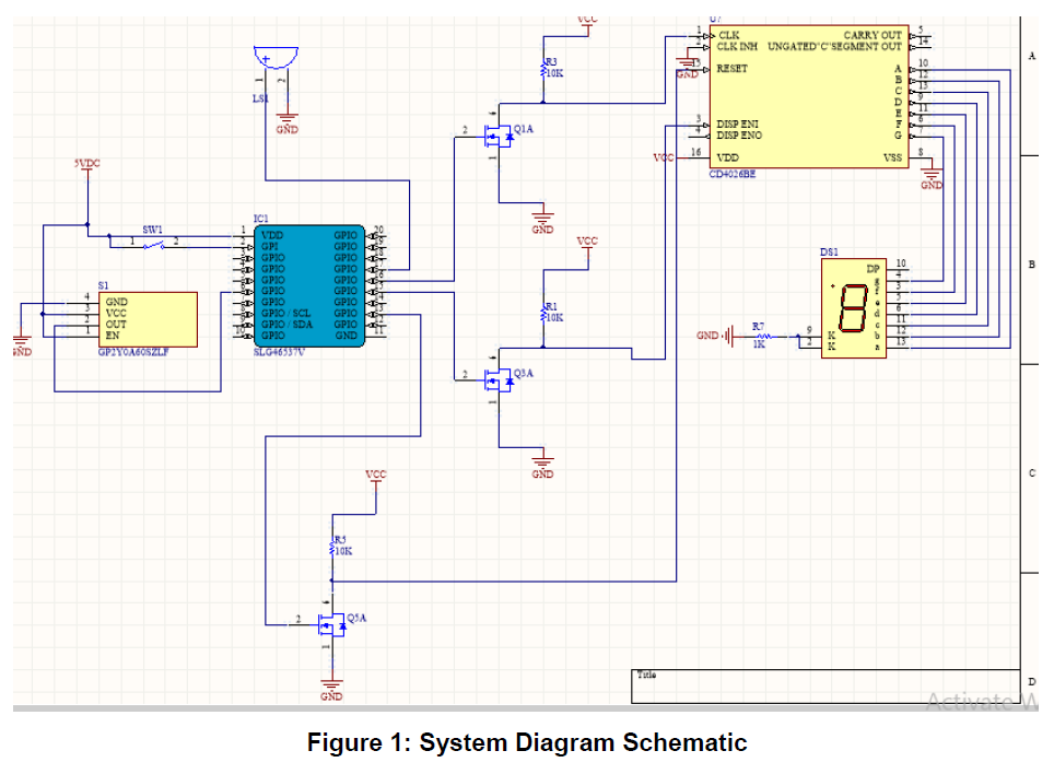
The functionality in this section relies heavily on the GreenPAK’s ASM block. It only uses 4 states, but it does use all 8 of the ASM’s outputs. Since the ASM has 4 unused states, we could use them to implement additional functionality. However, we will stick to the basics of the game
Figure 2 shows the ASM process started with just the press of the start button.
Each one of the stages is separated in the GreenPAK design to make them easier to explain.
Stage 0 consists only of the start button, which needs no further explanation.
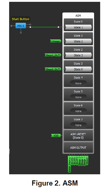
Stage 1 consists of a CLK divider that pulses every 512 milliseconds, which is used to generate the 3 starting beeps. It has a counter that will count 4 pulses of the CLK divider, and once it reaches the fourth pulse, it will trigger a signal to advance to Stage 2.
This counter will maintain a HIGH on its output until it is reset. We use its output to reset itself, and the signal State 0 to provide all the conditions necessary to reset the counter and ensure the functionality of the system in further iterations of the game. Figure 3 shows Stage 1, plus the Stage 3 condition to drive the buzzer.
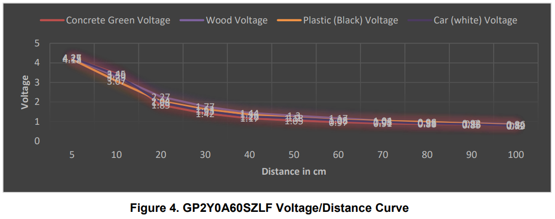
Stage 2 has two different components. The first is to keep track of the successful shots. At a hardware level, the ball will be detected by the GP2Y0A60SZLF proximity sensor, which will produce a certain voltage depending on the distance between itself and the ball. The GreenPAK is constantly measuring the voltage, but it will only react if two conditions are met: the GreenPAK detects a voltage greater than 4 V (selected using the GP2Y0A60SZLF table shown in Figure 4) and the system is in Stage 2.
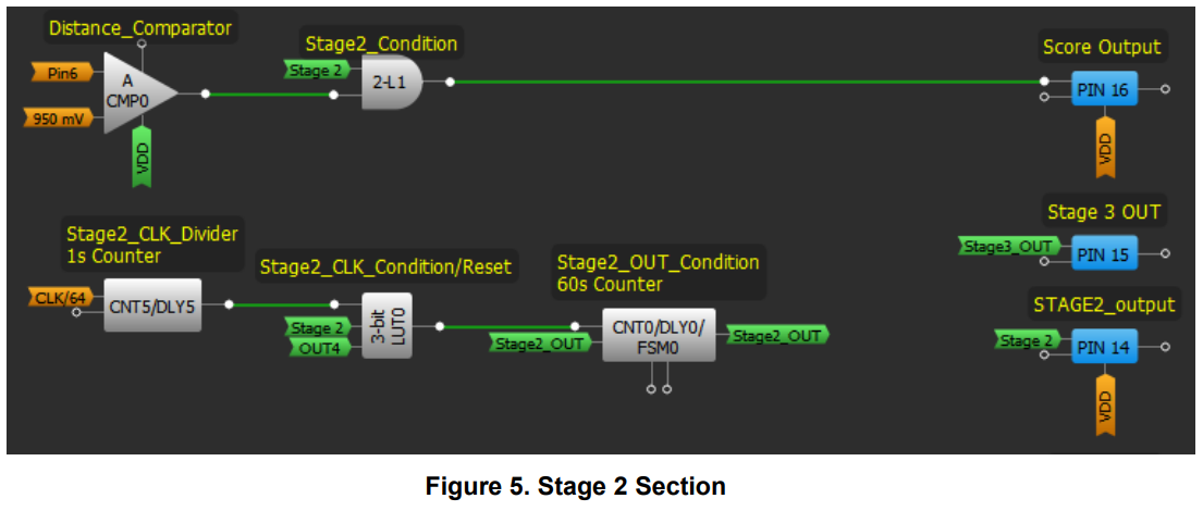
The second component of Stage 2 is to keep track of the 60 seconds in which the game is played. To do that we use a pair of counters and a LUT to create a 60 s timer. Figure 5 features both these processes and a very similar reset condition as the one presented in Stage 1.
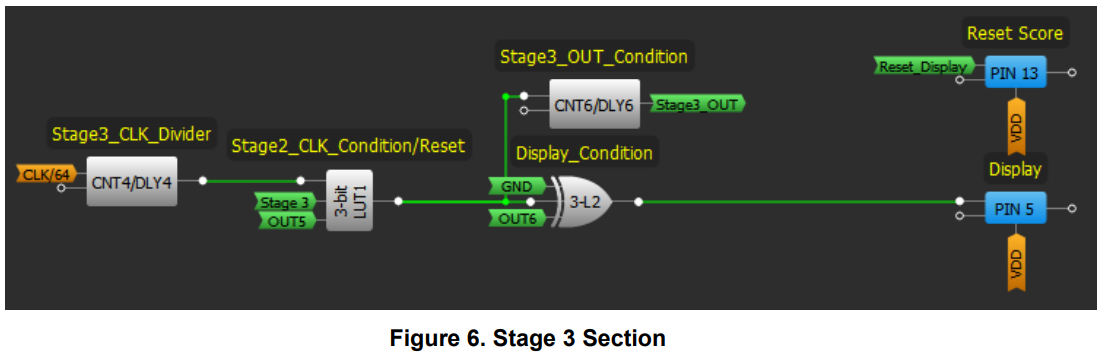
Stage 3 should emit a long beep and blink the display five times. To do this we again need to use a CLK divider. We configure it to pulse every 200 milliseconds and count 5 pulses. As the display is always HIGH during the game, we use an XOR block to make it blink. The condition of the long beep is visible in Figure 3, and the conditions of stage 3 are shown in Figure 6.
So far, the budget for the electronic parts of the system is $47.50 USD (plus shipping expenses). The overall budget will change depending on the materials of construction (wood, steel, glass fiber, etc.), but in general terms, the electronic parts are going to cost pretty much the same (unless we mass-produce which would certainly reduce the manufacturing price per unit).
To get a clearer picture, a device with similar characteristics but featuring 2 players can be found at a price of $360.00 USD plus shipping. Implementing a second player on our system would cost an additional $47.50 USD. Adding on $50.00 USD for the structure of the arcade machine would give us a price tag of $145.00 USD plus shipping. Again, this manufacturing price will go down depending on the production scale.
This concludes the main objective of this project. But if the intended use of this machine is as a for-profit arcade machine, the following designs may help with that implementation. Please note that all these solutions rely on more hardware and an additional GreenPAK.
Coin Detection
Solutions can be classified as hardware solutions or software solutions, or a mixture of both. The easiest way to implement coin detection would be to use sorting hardware and simple software implementation.
The hardware solution is a rail with a gap big enough to make rejected coins fall, but small enough to let the accepted coins pass. An infrared LED emitter and receiver will signal that a coin has passed.
This solution is simple enough to be implemented as an additional stage in the main routine or even using a LATCH block.
Using the LATCH means the HIGH value of the coin detector is going to be HIGH until we reset the LATCH using a reset condition, which will be Start_Button AND Token_Memory being HIGH at the same time.
Ticket Dispenser
For this, we are going to use a second GreenPAK and using the score output signal we are going to create a condition.
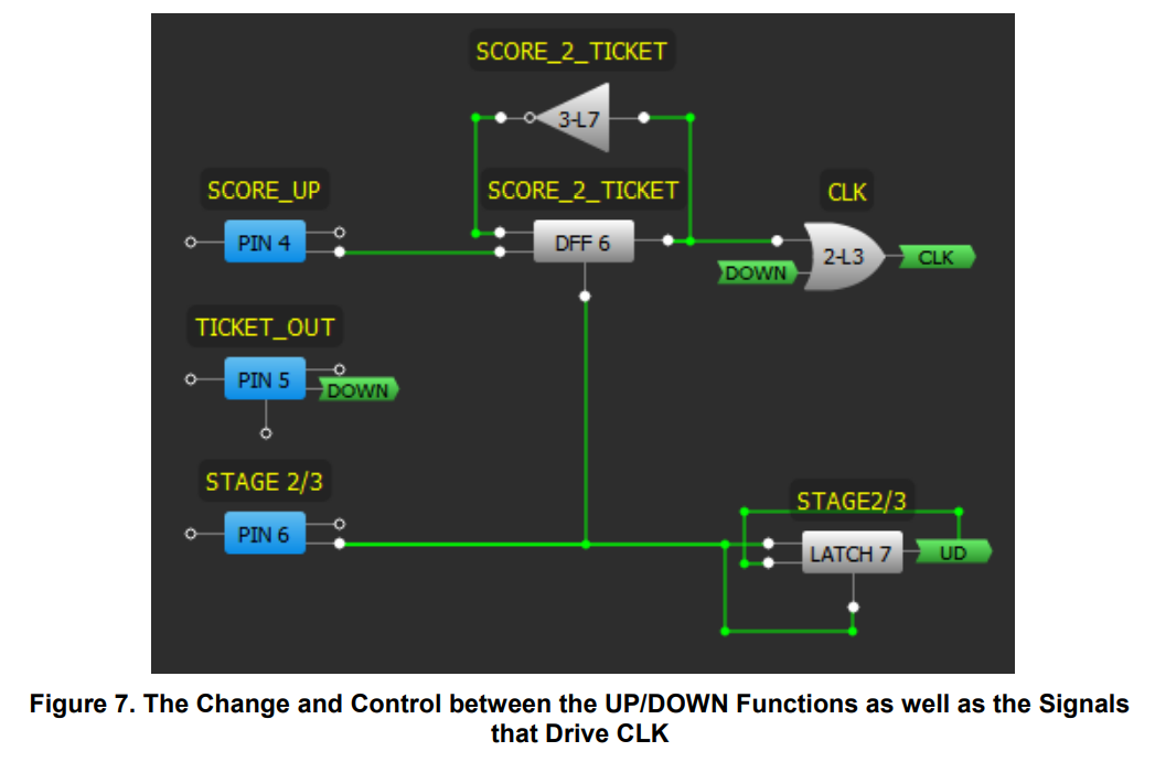
First, we have to define two signals: SCORE_UP and TICKET_OUT.
The first signal will go through a frequency divider, so every two points the CLK is going to finish one cycle.
The second signal is going to count one cycle with every pulse.
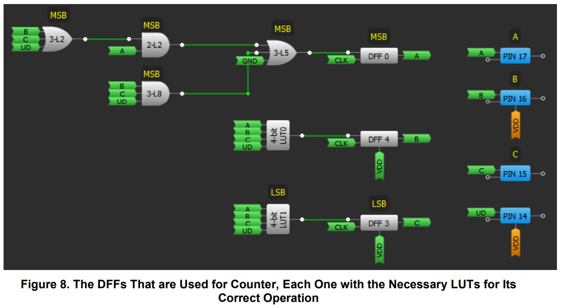
We also have a 3 bit UP/DOWN counter that we are going to use to monitor the number of tickets we are going to give away. This design is able to give away a maximum of 7 tickets if the player scores 14 points in the sixty seconds of the game.
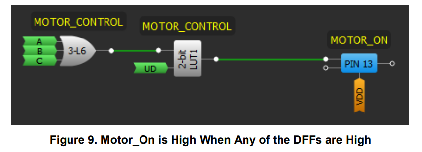
Once stage 2 is over, a motor is turned on as long as any of the 3 bits is HIGH. That counter is going to decrease once a ticket is sensed by the TICKET_OUT signal.
The stages of this design can be observed in Figure 7, Figure 8, and Figure 9.
It can only be turned on when the UD signal is LOW, which signals the counter should be going down.
The design of this ticket dispenser is simple but very useful. Since the truth table was designed to avoid overflow, the maximum stays at 7, even when the player scores more than 14 shots.
Conclusion
Using a Dialog GreenPAK SLG46537, we were able to successfully implement a homemade Basketball Arcade Machine which counts baskets and displays the score on 7-segment LEDs. It can also dispense tickets to the user. Thanks to GreenPAK and its GreenPAK Designer Software, this project was easy and affordable to implement.