This project presents a detailed description of achieving different animated indicator light patterns using SLG46620.
Recently, animated indicator front and rear LED patterns have become a norm in the automotive industry. These running LED patterns often represent a trademark of the automotive manufacturers and are used for visual aesthetics as well. The animations can be of different running patterns and can be implemented without any MCU using several discrete ICs.
The major requirements of such designs are reproducible performance during normal operation, an option to force all LEDs on, low power consumption, disabling the used LDO regulator during a fault, loading the LED driver before enabling it, etc. Additionally, the requirements can vary from one manufacturer to another. Moreover, usually in automotive applications, TSSOP ICs are usually preferred due to their robustness as compared to QFN ICs since these are known to be prone to solder fatigue issues, especially in harsh environments. Fortunately for this automotive application, Renesas provides a suitable GreenPAK™ IC, namely SLG46620, available in both QFN and TSSOP packages.
All of the requirements for the animated indicator LED patterns are currently met in the automotive industry using discrete ICs. However, the level of flexibility provided by GreenPAK IC is unmatched and can easily cater to the varying requirements of several manufacturers without any change in hardware design. Moreover, significant PCB footprint reduction and cost savings are also achieved.
In this project, a detailed description of achieving different animated indicator light patterns using SLG46620 is presented.
The complete design file can be found here. It was created in the GreenPAK Designer software (a part of the Go Configure™ Software Hub).
1. Industry Value
The turn signal patterns shown in this project are currently implemented in the automobile industry using a number of discrete ICs to control the sequence of automotive indicator LED patterns. The selected GreenPAK IC SLG46620 would replace at least the following components in the current industrial design:
- 1 No. 555 Timer IC (e.g. TLC555QDRQ1)
- 1 No. Johnson Counter (e.g. CD4017)
- 2 No. D-Type Positive-Edge-Triggered Flip-Flop (e.g. 74HC74)
- 1 No. OR gate (e.g. CAHCT1G32)
- Several passive components i.e. inductors, capacitors, resistors etc.
The selected GreenPAK IC SLG46620 would cost less than $0.50, so the total cost of the LED control circuitry decreases significantly. In addition, significant comparative PCB footprint reduction is also achieved.
2. System Design
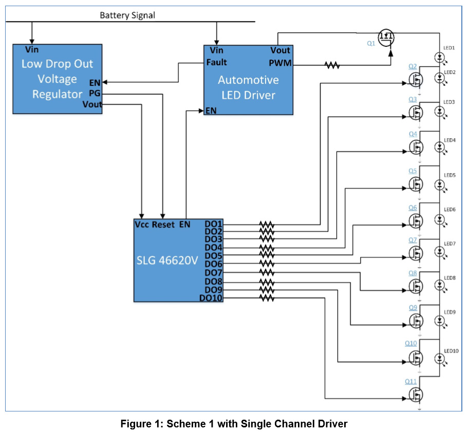
Figure 1 shows the diagram of the first proposed scheme. The major components of the scheme include a LDO voltage regulator, an automotive LED driver, the GreenPAK IC SLG46620, 11 logic-level MOSFETs and 10 LEDs. The LDO voltage regulator ensures that appropriate voltage is provided to the GreenPAK IC and if the battery voltage drops from a certain level the GreenPAK IC gets reset through the PG (Power Good) pin. During any fault condition, detected by the LED driver, the LDO voltage regulator gets disabled. The SLG46620 IC generates the digital signals to drive the indicator turn LEDs labelled 1-10 through the MOSFETs. Moreover, the selected GreenPAK IC also produces the enable signal for the single channel driver which in turn drives a MOSFET Q1 to load the driver running in constant current mode.
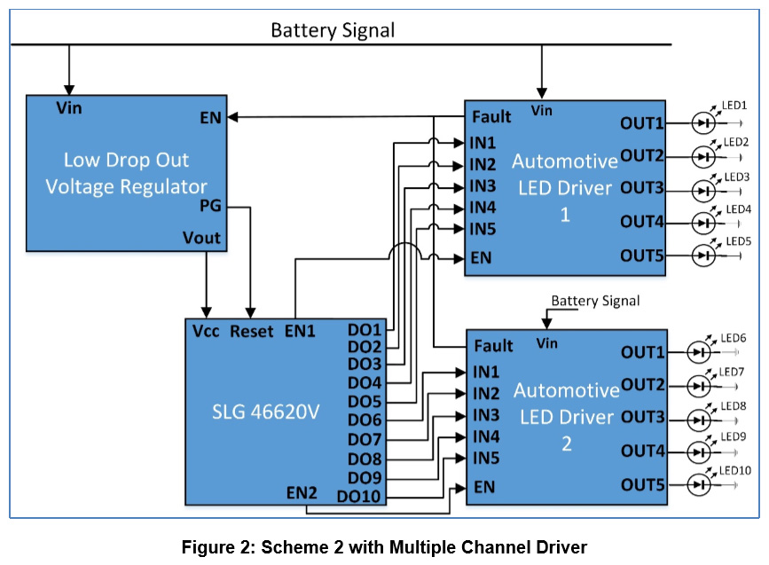
A variant of this scheme is also possible, where a multiple channel driver is employed, as shown in Figure 2. In this option, the driving current of each channel reduces as compared to the single channel driver.
3. GreenPAK Design
A suitable way to achieve the goal of flexible indicator LED patterns is to use a Finite State Machine (FSM) concept. Renesas provides several GreenPAK ICs that contain a built-in ASM block. However, unfortunately, all those GreenPAK ICs available in QFN packages are not recommended for harsh environments. So SLG46620 is chosen which is available in both QFN and TSSOP packaging.
Three examples are presented for three different LED animations. For the first two examples, we consider a single channel driver as shown in Figure 1. For the third example, we assume that multiple channel drivers are available, as shown in Figure 2, and each channel is used to drive a separate LED. Other patterns can also be obtained using the same concept.
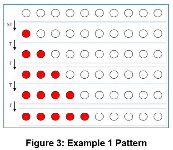
In the first example design, LEDs from 1-10 are sequentially turned on one after the other once a certain programmable time period expires as shown in Figure 3.
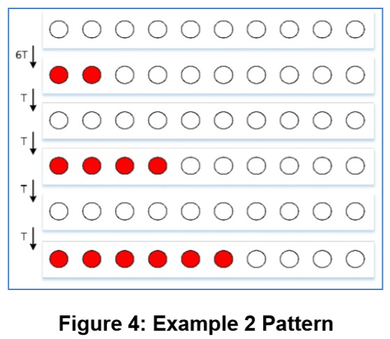
In the second example design, 2 LEDs are sequentially added in the pattern as shown in Figure 4.
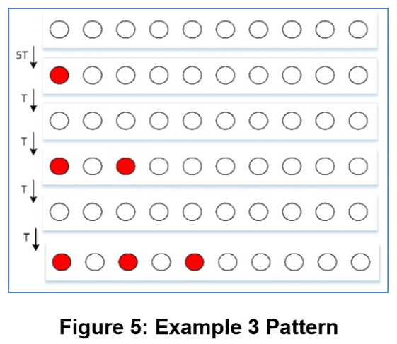
Figure 5 depicts how alternate LEDs are sequentially added in the pattern in the third proposed design.
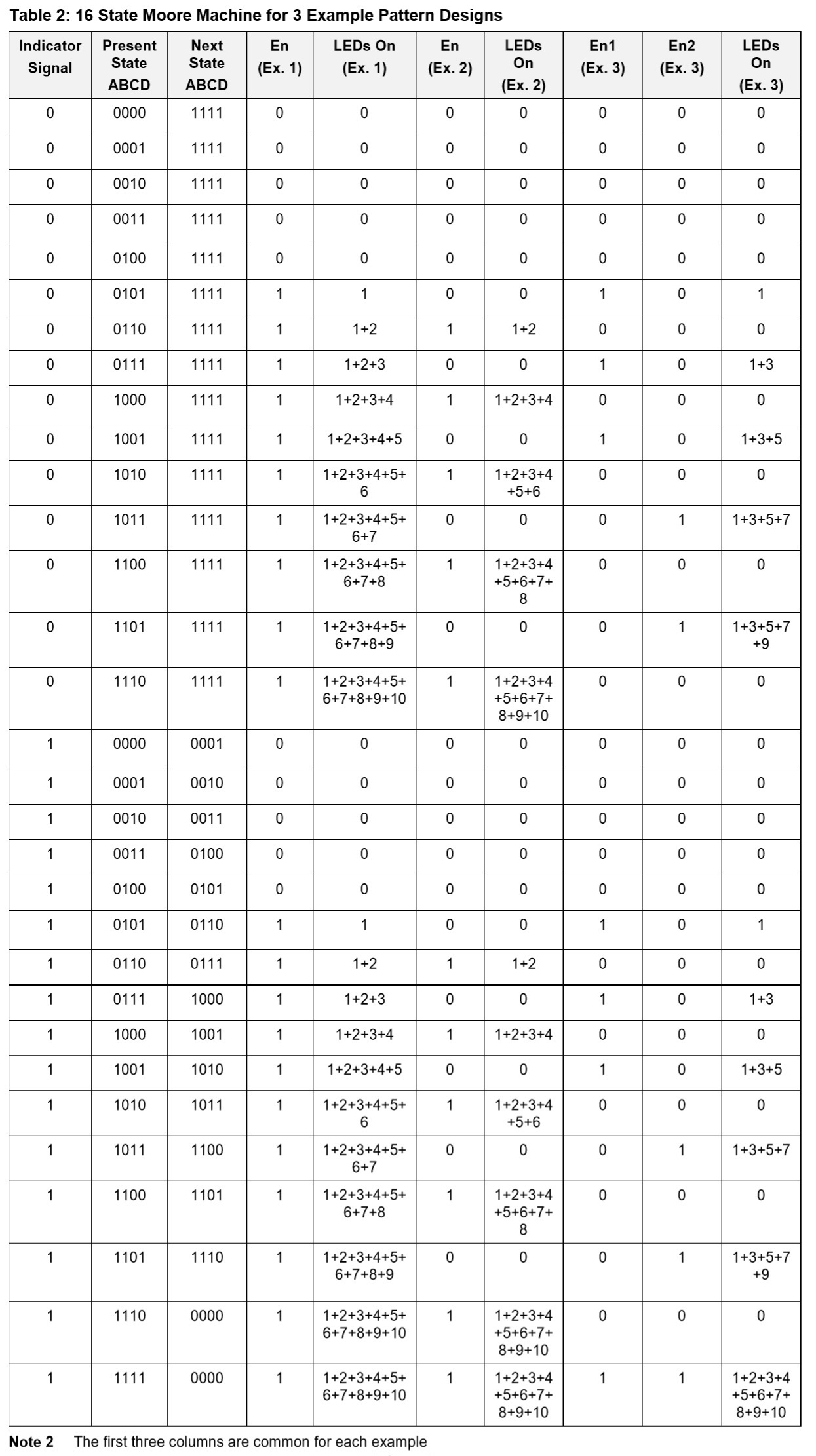
Since there is no built-in block of ASM available in SLG46620, a Finite State Moore Machine is developed using the available blocks namely counter, DFFs and LUTs. A 16 state Moore Machine is developed using Table 2 for the three examples. In Table 2, all the bits of the present state and the next state are given. Moreover, the bits for all the output signals are also provided. From Table 2 the equations of the next state and all the outputs are evaluated in terms of the present state bits.
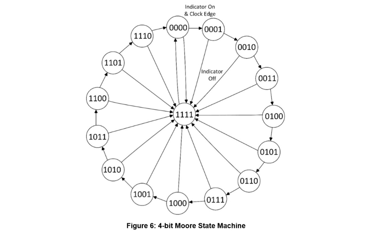
At the core of the development of 4-bit Moore Machine are 4 DFF blocks. Each DFF block functionally represents one bit of the four bits: ABCD. When the indicator signal is high (corresponding to an on indicator switch), a transition from one state to the next is required at each clock pulse, thus generating different LED patterns as a result. On the other hand, when the indicator signal is low, a stationary pattern, having all the LEDs on in each design example is the goal.
Figure 3 shows the functionality of the developed 4-bit (ABCD) Moore Machine for each example. The basic idea of the development of such FSM is to represent each bit of the next state, the enable signal and each output pin signal (assigned for the LEDs) in terms of the present state. This is where the LUTs contribute. All the 4 bits of present state are fed to different LUTs to basically achieve the required signal in the next state at the edge of a clock pulse. For the clock pulse, a counter is configured to provide a pulse train with a suitable period.
For each example, each bit of the next state is evaluated in terms of the present state using the following equations derived from K-Maps:
A = D' (C' + C (A B)') & IND + IND'
B = C' D + C D' (A B)' & IND + IND'
C = B' C D + B (C' + A' D') & IND + IND'
D = A B' + A' B C D + A B C' & IND + IND'
where IND represents the indicator signal.
Further details of each of the three examples are given below.
Design Example 1
The equations of the enable signal and the LED driving signals for the 1st example, with each LED turning on sequentially using the scheme in Figure 1, are as shown below.
En = A + A' B (C+D)
DO1 = A' B C' D
DO2 = A' B C D'
DO3 = A' B C D
DO4 = A B' C' D'
DO5 = A B' C' D
DO6 = A B' C D'
DO7 = A B' C D
DO8 = A B C' D'
DO9 = A B C' D
DO10 = A B C
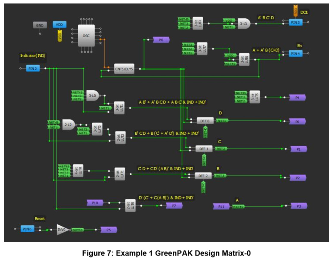
In Figure 7, the Matrix-0 GreenPAK design of Example 1 is shown. 4 DFFs are used to develop the 4-bit Moore Machine. DFFs with reset option (3 from Matrix-0 and 1 from Matrix-1) are selected so that the Moore Machine can be reset conveniently. A counter, with a suitable time period of 72 mS, is configured to change the state of the Machine after each period. LUTs with appropriate configurations are used to derive functions for the DFFs inputs, Driver Enable Signal (En), and the output pins: DO1-DO10.
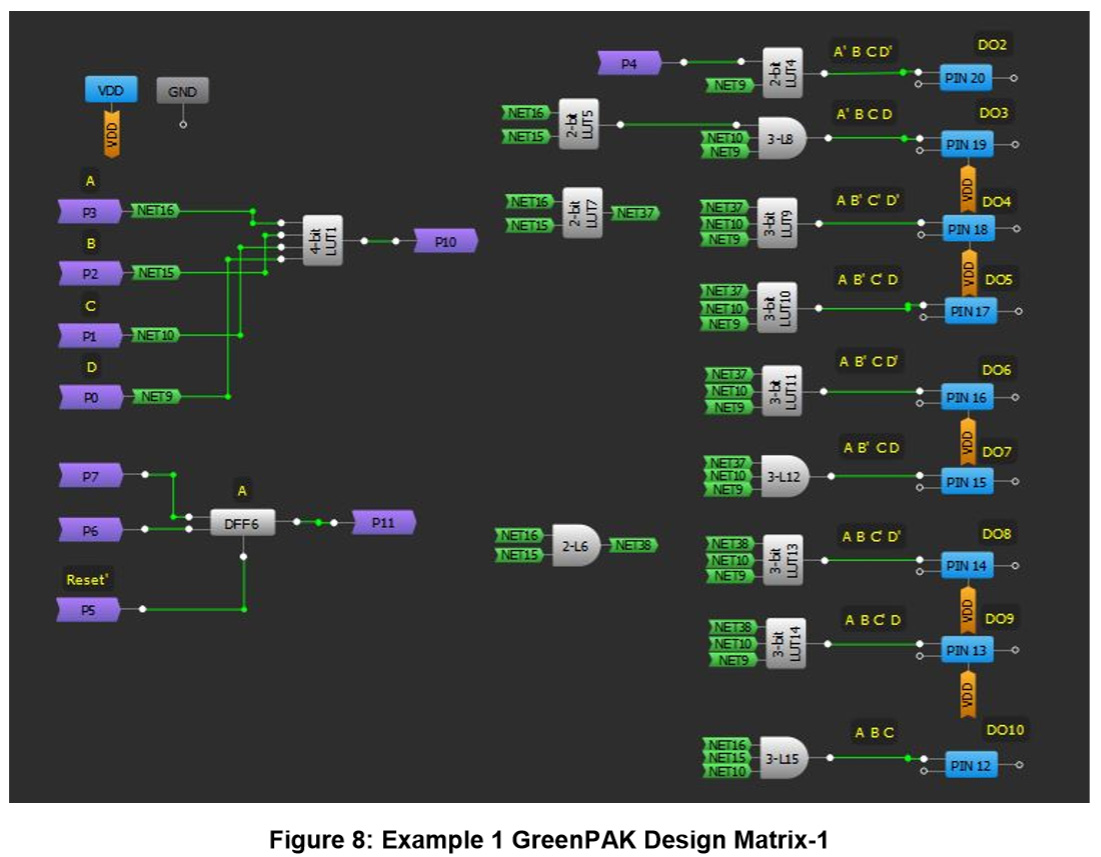
In the Matrix shown in Figure 8, the rest of the GreenPAK resources are utilized to complete the design using the methodology described earlier. The figures are appropriately labeled for clarity.
Design Example 2
The equations of the enable signal and the LED driving signals for the 2nd example, with two LEDs adding in the sequential pattern using the scheme in Figure 1, are shown below.
En = D' (A' B C + A B' C' + A B' C + A B) + A B C
DO1 = 0
DO2 = A' B C D'
DO3 = 0
DO4 = A B' C' D'
DO5 = 0
DO6 = A B' C D'
DO7 = 0
DO8 = A B C' D'
DO9 = 0
DO10 = A B C
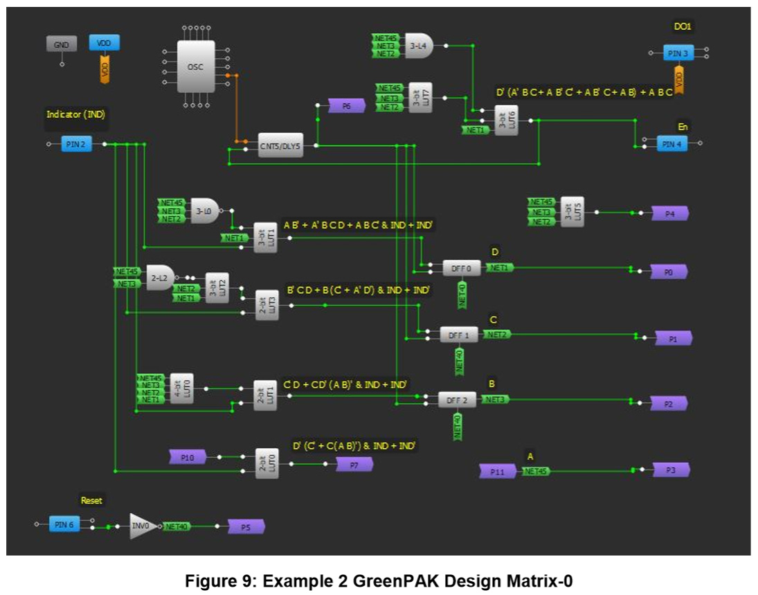
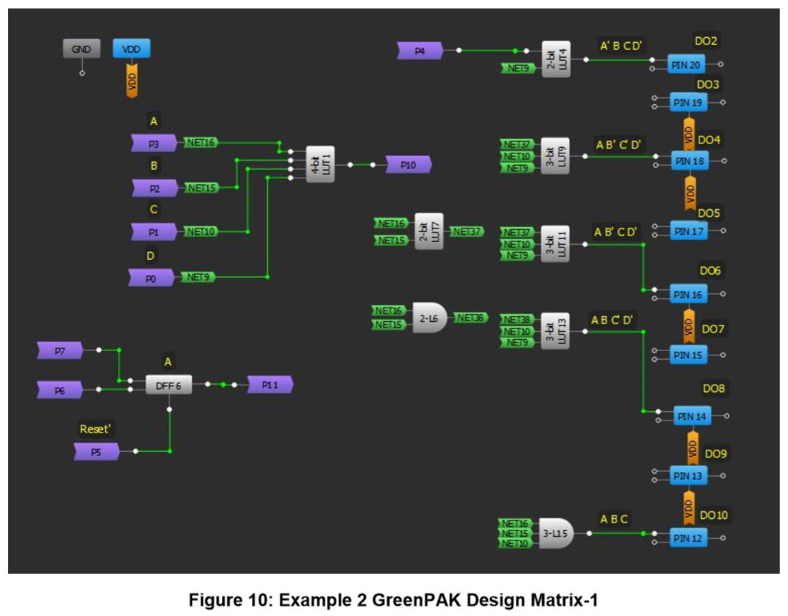
In Figure 9 and Figure 10, the Matrix-0 & 1 GreenPAK designs of Example 2 are presented. The basic design is similar to the Example 1 design. The major differences, in comparison, are in the Driver Enable (En) function and no connections of DO1, DO3, DO5, DO7, and DO10, which are pulled down in this design.
Design Example 3
The equations of the enable signal and the LED driving signals for the 3rd example, generating alternate LED sequential addition pattern using the scheme in Figure 2, are given below.
En1 = (A' B C' + A B' C' + B C) D
En2 = (A B' C + A B) D
DO1 = D (A+B)
DO2 = A B C D
DO3 = D (A+ C B)
DO4 = A B C D
DO5 = D A
DO6 = A B C D
DO7 = D A (C' B + C)
DO8 = A B C D
DO9 = D A B
DO10 = A B C D
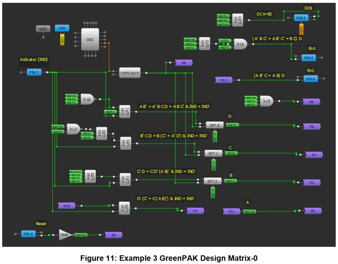
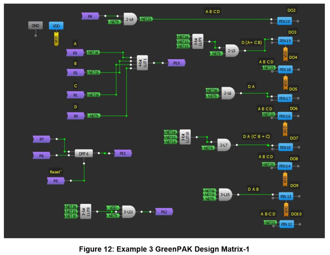
In Figure 11 and Figure 12, the Matrix-0 & 1 GreenPAK designs of Example 3 are presented. In this design, there a two separate Driver Enable Signals (En1 & En2) for Drivers 1 & 2. Moreover, the output pins are connected to the outputs of appropriately configured LUTs.
This concludes the GreenPAK design part of Example 1, Example 2, and Example 3.
4. Experimentation Results
A convenient way to test the designs of Example 1, Example 2 and Example 3 is experimentation and visual inspection. The temporal behavior of each scheme is analyzed using a logic analyzer and the results are presented in this section.
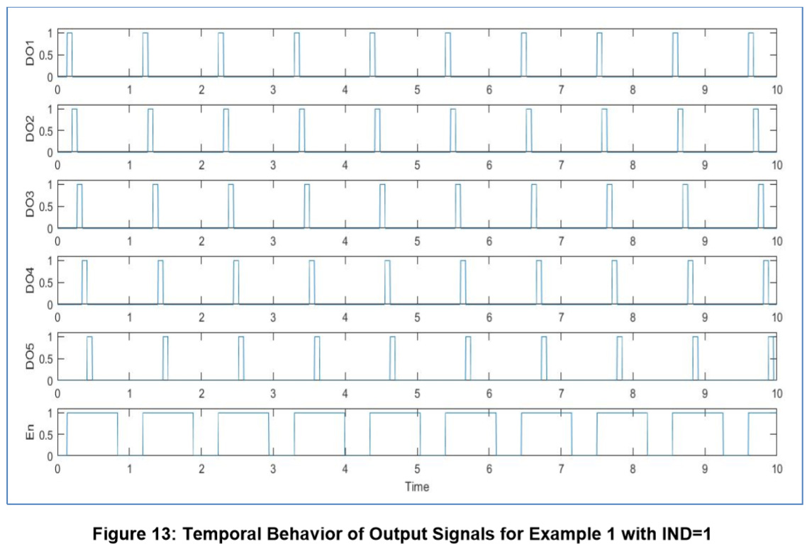
Figure 13 shows the temporal behavior of different output signals for Example 1 whenever the indicator is turned on (IND=1). It can be observed that the signals for the output pins DO1-DO5 sequentially turn on after the other after a set time period expires in accordance with Table 2. The pattern of the signals provided to the pins DO6-DO10 is also similar. The Driver Enable (En) signal turns on when any of the signals DO1-DO10 is turned on and otherwise it is off. During the animation, whenever the indicator signal goes low (IND=0), the En and DO10 signals turn on and remain logical high. In short, the results meet the requirements and validate the theoretical proposals for Example 1.
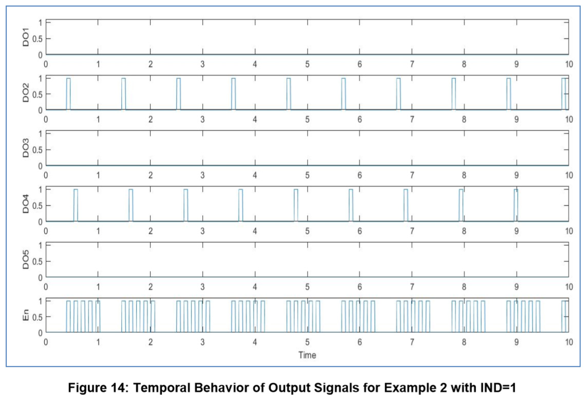
In Figure 14, the timing diagram of different output signals for Example 2, with the indicator signal turned on (IND=1), is depicted. It is observed that the signals for the output pins DO1-DO5 are turned on alternately in a sequence after some time period in agreement with Table 2. The pins DO1, DO3 and DO5 remain low, whereas the signals for the DO2 and DO4 alternately turn on sequentially. The same patterns for DO6-DO10 are also observed (not shown in the figure due to limited number of analyzer inputs). Whenever any of the signals DO1-DO10 is on, the Driver Enable (En) signal also turns on which otherwise remains off. Throughout the animation, whenever the indicator signal goes low (IND=0), the En and DO10 signals turn on and remain logical high. The results meet the requirements and the theoretical ideas for Example 2 exactly.
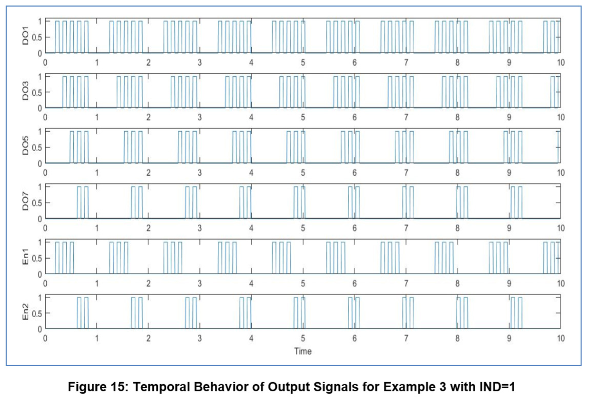
Figure 15 shows, the timing diagram of different output signals for Example 3, with the indicator signal turned on (IND=1). It can be observed that the signals for the output pins DO1-DO7 turn on as shown in Table 2. Moreover, pin DO9 signal also behaves according to Table 2 (not shown in the figure). Pins DO2, DO4, DO6, DO8, and DO10 remain low. The En1 turns logical high whenever a signal from DO1, DO3, and DO5 is on and En2 turns logical high whenever a signal from DO7 and DO9 goes high. During the entire animation, whenever the indicator signal goes low (IND=0), all the output signals: En1, En2, and DO1-DO10 turn on and remain logical high. Therefore, it can be concluded that the results fulfill the requirements and the theoretical proposals for Example 3.
Conclusion
A detailed description of various automotive turn signal schemes with animation has been presented. A suitable GreenPAK IC SLG46620 was chosen for this application since it is also available in the TSSOP package which is advisable for harsh environment industrial applications. Two major schemes, using single and multiple channel automotive drivers, are presented to develop flexible sequential LED animation models. Appropriate Finite State Moore Machine models are developed to generate the desired animations. For validation of the developed model, convenient experimentation has been carried out. It is established that the functionality of the developed models agrees with the theoretical design.