DIY system to detect the presence of any object in a restricted area
Things you need
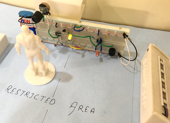
A light fence circuit is used to detect the presence of any human or object in a particular area. The detecting range of Light Fence Circuit is about 1.5 to 3 meters. It’s quite simple to design the circuit using LDR and Op-amp. This portable circuit can work smoothly with a commonly available 9V battery and the alarm sound generated from the buzzer is loud enough to detect the presence of a human, vehicle or object.
What is a Light Dependent Resistor (LDR) or Photoresistor?
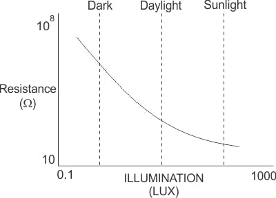
A Light Dependent Resistor (also known as a photoresistor or LDR) is a device whose resistivity is a function of the incident electromagnetic radiation. Hence, they are light-sensitive devices. They are also called as photoconductors, photoconductive cells or simply photocells.
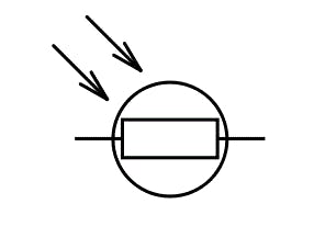
They are made up of semiconductor materials that have high resistance. There are many different symbols used to indicate a photoresistor or LDR, one of the most commonly used symbol is shown in the figure below. The arrow indicates light falling on it.
555 Timer
The 555 timer IC is one of the most used IC in electronics, especially for triggering purposes. Be it a simple project involving a single 8-bit micro-controller and some peripherals or a complex one involving system on chips (SoCs), 555 timer working is involved. Depending on the manufacturer, the standard 555 timer package includes 25 transistors, 2 diodes and 15 resistors on a silicon chip installed in an 8-pin mini dual-in-line package (DIP-8). Variants consist of combining multiple chips on one board. However, 555 is still the most popular.
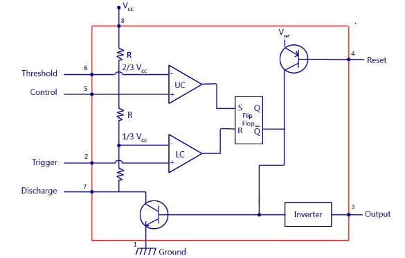
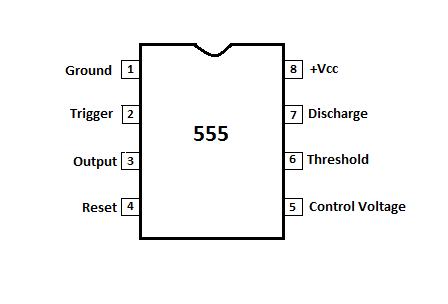
Pin Configuration of 555 Timer
For a 555 timer working as a flip flop or as a multi-vibrator, it has a particular set of configurations.
Pin 1. Ground: This pin should be connected to the ground.
Pin 2. TRIGGER: Trigger pin is dragged from the negative input of comparator two. The Lower comparator output is connected to the SET pin of the flip-flop. A negative pulse (< Vcc/3) on this Pin sets the Flip flop and output goes High.
Pin 3. OUTPUT: This pin also has no special function. This is the output pin where the Load is connected. It can be used as a source or sink and drive up to 200mA current.
Pin 4. Reset: There is a flip-flop in the timer chip. The reset pin is directly connected to MR (Master Reset) of the flip-flop. This is an active Low pin and normally connected to VCC for preventing accidental Reset.
Pin 5. Control Pin: The control pin is connected from the negative input pin of comparator one. Output Pulse width can be controlled by applying a voltage at this Pin, irrespective of the RC network. Normally this pin is pulled down with a capacitor (0.01uF), to avoid unwanted noise interference with the working.
Pin 6. THRESHOLD: Threshold pin voltage determines when to reset the flip-flop in the timer. The threshold pin is drawn from the positive input of the upper comparator. If the control pin is open, then a voltage equal to or greater than VCC*(2/3) will reset the flip-flop. So the output goes low.
Pin 7. DISCHARGE: This pin is drawn from the open collector of the transistor. Since the transistor (on which discharge pin got taken, Q1) got its base connected to Qbar. Whenever the output goes low or the flip-flop gets reset, the discharge pin is pulled to ground and capacitor discharges.
Pin 8. Power or VCC: It is connected to positive voltage (+3.6v to +15v).
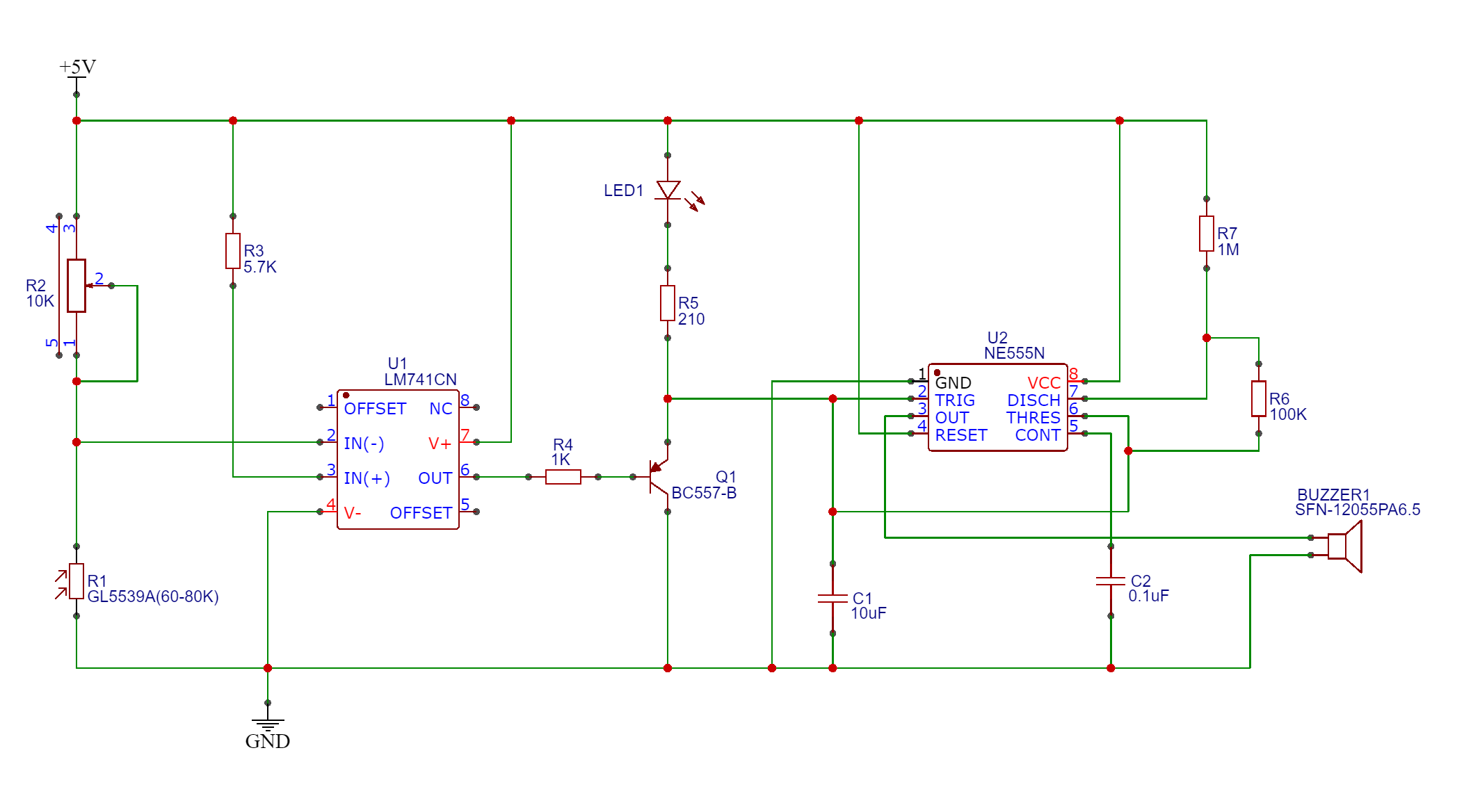
Circuit Diagram
The complete circuit diagram for Automatic Fence Lighting with Alarm is shown above. LDR is placed facing towards the entrance and a potentiometer is used to adjust the sensitivity of the device. You can also add a switch between the negative pin of the battery and LDR’s grounded pin to control this security system manually.
Working
Here, the op-amp IC is used as a voltage comparator and the 555 timer IC is placed in an astable mode. The LDR and the potentiometer are creating a voltage divider circuit. The output of this divider circuit will change according to the intensity of light falls on the LDR. The divider is connected to the inverting pin of the Op-amp IC. The non-inverting pin is connected with supply through a 5.7Kohm resistor, so the voltage value at the non-inverting is fixed. You can replace this resistor with a 10K potentiometer to adjust the voltage as per the requirement.
We can adjust the sensitivity of the device by using the potentiometer VR1 connected in series with the LDR. When the voltage at the non-inverting input is greater than or equal to the reference voltage the output (at pin 6) of the op-amp IC output (PIN 6) goes HIGH. Learn more about working of op-amp by following the various op-amp based circuits.
According to the circuit diagram, when LDR detects any activity the output of the Op-amp IC goes LOW, and PNP transistor T1 starts conducting. Hence, the LED starts glowing and the 555 timers IC gets triggered. Here, 555 timer IC is in Astable mode and a preset time delay is provided by R3, R5, and C1.
So whenever some person or object enters the prohibited area, his shadows will be sensed by the LDR and the circuit triggers the alarm.