Check out how to use a GreenPAK IC to monitor the ambient conditions
of a transformer.
Below we described steps needed to understand how the solution has been programmed to create the solution. However, if you just want to get the result of programming, download GreenPAK™ Designer software to view the already completed GreenPAK Design File. Plug the GreenPAK Development Kit to your computer and hit the program to design the device.
This project will describe how to use a GreenPAK IC to monitor the ambient conditions of a transformer. If any increase in the transformer’s nominal operating conditions is detected, the monitor circuit will set off an alarm buzzer. A cooling fan will be turned when the transformer temperature is above the normal operating temperature. This application will monitor basic transformer parameters such as temperature, oil level, and the gases generated by the polychloropolyfoloromethylbenzene transformer oil.
Implementation Background
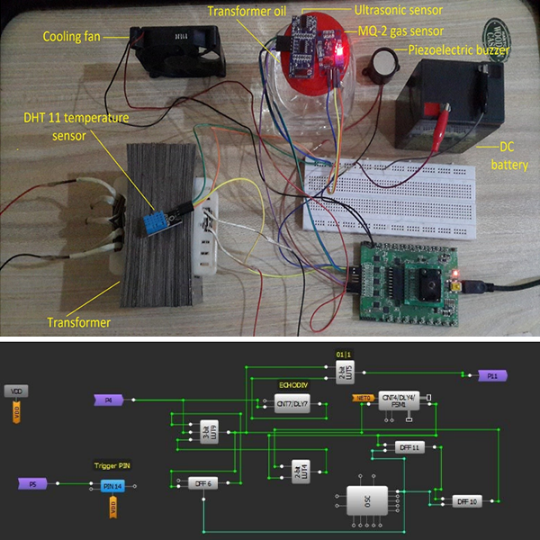
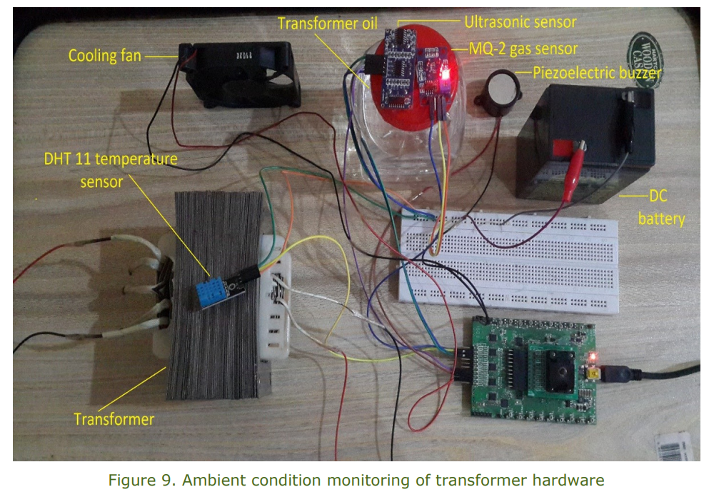
In this implementation, we will be using an ultrasonic sensor, MQ-2 gas sensor, DHT 11 temperature sensor, cooling fan, a buzzer, and an SLG46620V GreenPAK IC.
Explanation
A power system consists of power generation, transmission, and distribution. A transformer is one of the main components of the power system. Transformers are devices used in electrical circuits to change the voltage of electricity flowing in the circuit. Transformers can be used to either increase the voltage (called stepping up) or decrease the voltage (stepping down).
Energy is lost in the process of transmitting electricity long distances, such as during the journey from a power plant to your home. Less energy is lost if the voltage is very high, so electrical utilities use high voltage in long-distance transmission wires. The power transmitted along the line is equal to the voltage times the current. The higher the voltage, the lower the current that must flow within the transmission lines to deliver the same power. Lower currents produce much less heating and much less power loss. However, the high voltage is too dangerous for home use.
Therefore, electrical utilities use transformers to change the voltage of electricity as it travels from the power plant to your home. First, the voltage of electricity coming from the power plant is stepped up to the right level for long-distance transmission, using transformers. Later, more transformers step down the voltage before it enters your home.
There are certain necessary conditions that are required for the appropriate transformer operation. For example, when a transformer is overloaded, its body gets hot and its efficiency decreases. A cooling mechanism is required for efficient operation, so cooling fans are used in order to reduce the temperature.
The temperature rise of a transformer can be estimated by the following formula:
ΔT = (PΣ / AT)^0.833
Where:
ΔT = temperature rise in °C
PΣ = total transformer losses (power lost and dissipated as heat) in mW
AT= surface area of the transformer in cm2
The mineral oil that is used in the transformer is polychloropolyfoloromethylbenzene. It has two advantages:
Cooling
When the transformer gets hot, oil is circulated in the windings so that cooling takes place.
Insulation
The mineral oil also provides insulation between the windings.
Transformer oils are subject to electrical and mechanical stresses while a transformer is in operation. In addition, there is contamination caused by the chemical interactions with windings and other solid insulation, catalyzed by high operating temperatures. The original chemical properties of transformer oil change gradually, rendering it ineffective for its intended purpose after many years. Oil in large transformers and electrical apparatuses is periodically tested for its electrical and chemical properties, to make sure it is suitable for further use. Sometimes the oil’s condition can be improved by filtration and treatment.
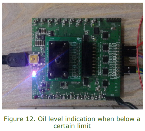
During the continuous running of the transformer, the oil level decreases. The oil level should not fall below a particular level, otherwise, proper cooling of the transformer will not take place.
Algorithm Description
The transformer under consideration steps down voltage levels from 220 V to 15 V. The transformer mineral oil is in a small container, and the ultrasonic sensor and MQ-2 gas sensor are attached on the top side of it. A temperature sensor is also attached to the body of the transformer to measure its operating temperature.
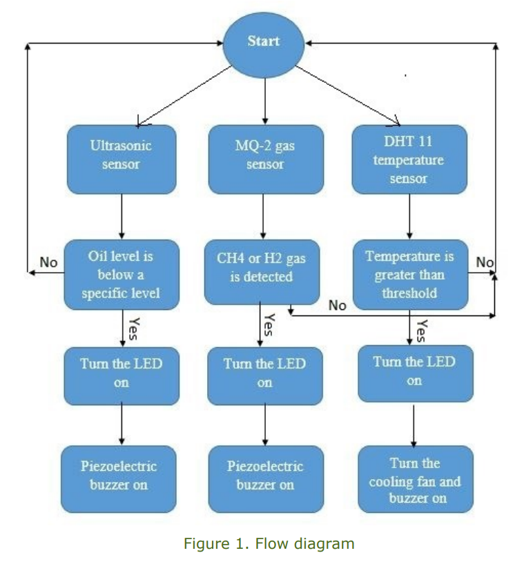
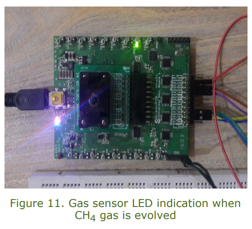
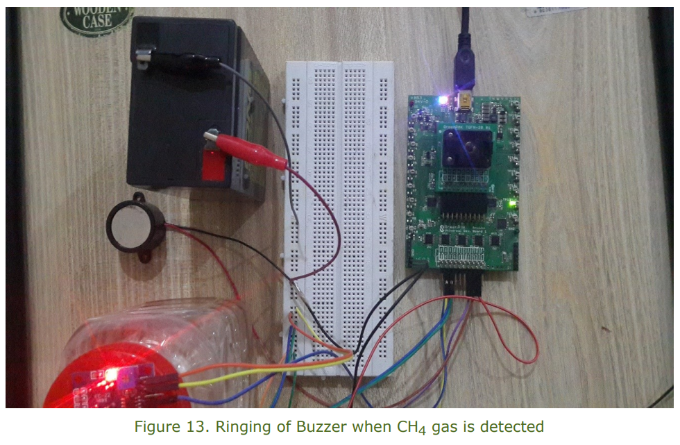
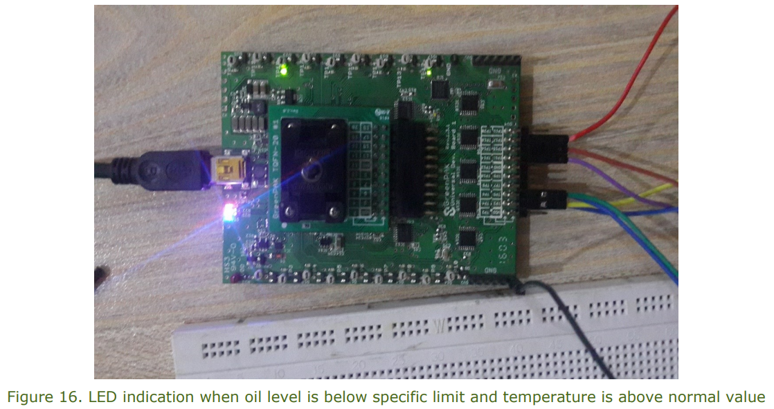
The three sensor outputs from the ultrasonic sensor, gas sensor, and temperature sensor are sent to the GreenPAK CMI inputs. The designed algorithm in the GreenPAK takes these inputs and generates outputs. At the output side, the cooling fan, piezoelectric buzzer, and built-in GreenPAK LEDs are connected. The ultrasonic sensor provides information about the level of oil in the container. If the oil level is below a certain limit, the LED indicator and buzzer are turned on. The MQ-2 gas sensor will detect the hydrogen and methane (CH4) gases emitted from the oil. These gases reveal the nature of internal faults in the transformer. Since oil is circulated within the transformer for cooling and insulation purposes, when a fault occurs, its composition changes, and different gases are generated. Here, the presence of methane and hydrogen gas will be indicated by a buzzer as well as from an LED.
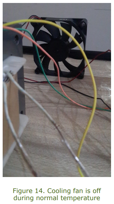
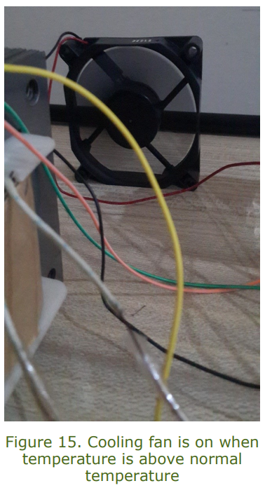
The temperature sensor detects the transformer body temperature. If it is greater than normal operating value (i.e., 40° C), a cooling fan is turned on so that transformer body can regain the normal temperature. The buzzer will also be turned on in this case. The algorithm flow diagram is shown below.
The explanation of used components is given below.
Ultrasonic Sensor HC-SR04
An ultrasonic sensor is a device that can measure the distance to an object by using sound waves. It measures distance by sending out a sound wave at a specific frequency and listening for that sound wave to bounce back. By recording the elapsed time between the sound wave being generated and the sound wave bouncing back, it is possible to calculate the distance between the sonar sensor and the object. Since it is known that sound travels through air at about 344 m/s, you can take the time for the sound wave to return and multiply it by 344 meters to find the total round-trip distance of the sound wave. Round-trip means that the sound wave traveled two times the distance to the object before it was detected by the sensor; it includes the 'trip' from the sonar sensor to the object and the 'trip' from the object to the ultrasonic sensor. The ultrasonic sensor is shown below.
It consists of four pins: Vdd, GND, Trigger, and Echo. Vdd is for DC power input. Whenever a pulse is applied on the Trigger pin, the sensor emits a waveform of ultrasound from one of the roboticeye-like outlets in the forward direction. When reflected back from obstacles, this waveform is detected by the other “eye” and is sensed by the controller from the Echo pin. The larger the distance between the sensor and an obstacle, the longer the pulse sensed at the Echo pin. The time the pulse remains on is equal to the time taken by the sonar pulse to travel from the sensor and return back, divided by two. When the sonar is triggered, the internal timer starts and continues until it detects the reflected wave. This time is then divided by two because the actual time it took the sound wave to reach the obstacle was half the time that the timer was on.
The following formula is used to find the time duration:
The time for the sound wave to reach the obstacle is then found by the following relation:
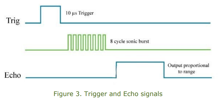
In order to generate the ultrasound, you need to set the Trigger pin in a HIGH state for 10 µs. That will send out an 8 cycle sonic burst which will travel at the speed of sound, and, after reflection from the obstacle, will be received at the Echo pin. The Echo pin will output the time in microseconds that the sound wave traveled.
MQ-2 Gas Sensor
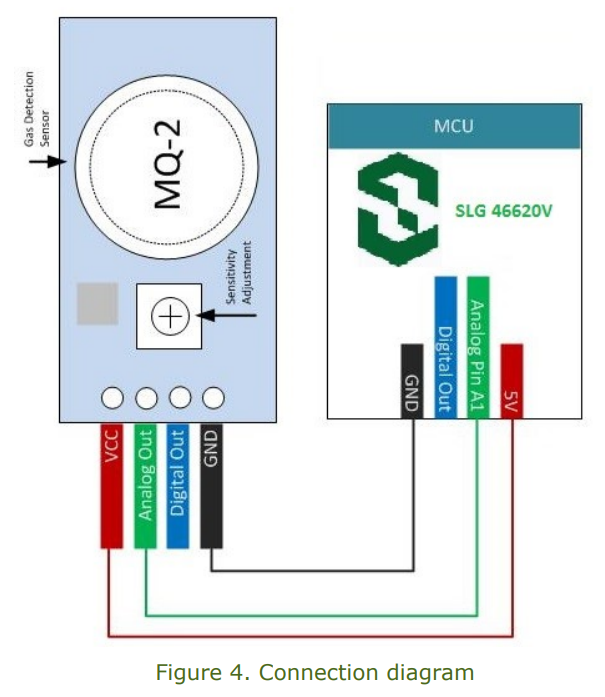
The MQ series of gas sensors use a small heater with an electrochemical sensor. They are sensitive to a range of gases and are used indoors at room temperature. The output is an analog signal that can be read with an analog input pin of the GreenPAK CMIC. The MQ-2 Gas Sensor module is useful for gas leakage detection in homes and industry. It can detect LPG, i-butane, propane, methane, alcohol, hydrogen, and smoke. Some modules have a built-in variable resistor to adjust the sensitivity of the sensor. The diagram of the MQ-2 gas sensor and connection to SLG46620V is shown below.
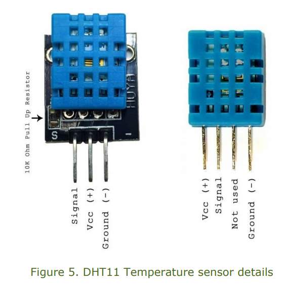
The DHT11 Sensor features a temperature & humidity sensor combination with a calibrated signal output. By using an exclusive digital-signal-acquisition technique and temperature and humidity sensing technology, it ensures high reliability and excellent long-term stability. This sensor includes a resistive-type humidity measurement component and an NTC temperature measurement component, and connects to a high-performance 8-bit microcontroller, offering excellent quality, fast response, anti-interference ability, and cost-effectiveness. Each DHT11 element is strictly calibrated in a laboratory that is extremely accurate on humidity calibration. The calibration coefficients are stored as programs in the OTP memory, which are used by the sensor’s internal signal detecting process.
The single-wire serial interface makes system integration quick and easy. Its small size, low power consumption, and up-to-20 meter signal transmission makes it the best choice for various applications, including those most demanding ones. The component is 4-pin single row package. It’s convenient to connect, and special packages can be provided according to users’ request.
DHT11 Specifications:
- 3 to 5 V power
- Max. 2.5 mA during conversion
- Humidity range 20-80% with 5% accuracy
- Temperature range 0-50°C with ±2°C accuracy
Pinout:
- VCC (3 to 5 V power)
- Data out
- NC
- GND
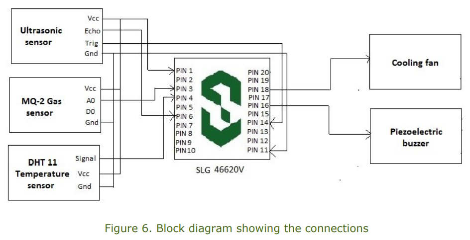
The block diagram showing the connections among SLG46620V and ultrasonic sensor, MQ-2 gas sensor, DHT11 temperature sensor, cooling fan, and the piezoelectric buzzer is shown below.
GreenPAK Design Description
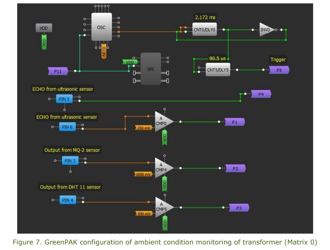
The design schematic of Matrix 0 is shown below.
In Matrix 0, the outputs from the ultrasonic sensor, MQ-2 gas sensor, and DHT11 temperature sensor have been connected to the comparator inputs separately. The outputs of comparators are then assigned to the output ports P1, P2, and P3. The Trigger input for the ultrasonic sensor has also been created using the P11 input port from Matrix 1. Different counters, flip-flops, inverters, oscillators, and look up tables have been used for the creation of Trigger input.
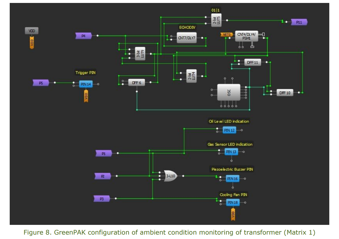
In Matrix 1, the input from P1, P2, and P3 ports have been taken and then applied to the look-up table input. It is then assigned to the output pins and LEDs. The output pins are connected to the piezoelectric buzzer and cooling fan.
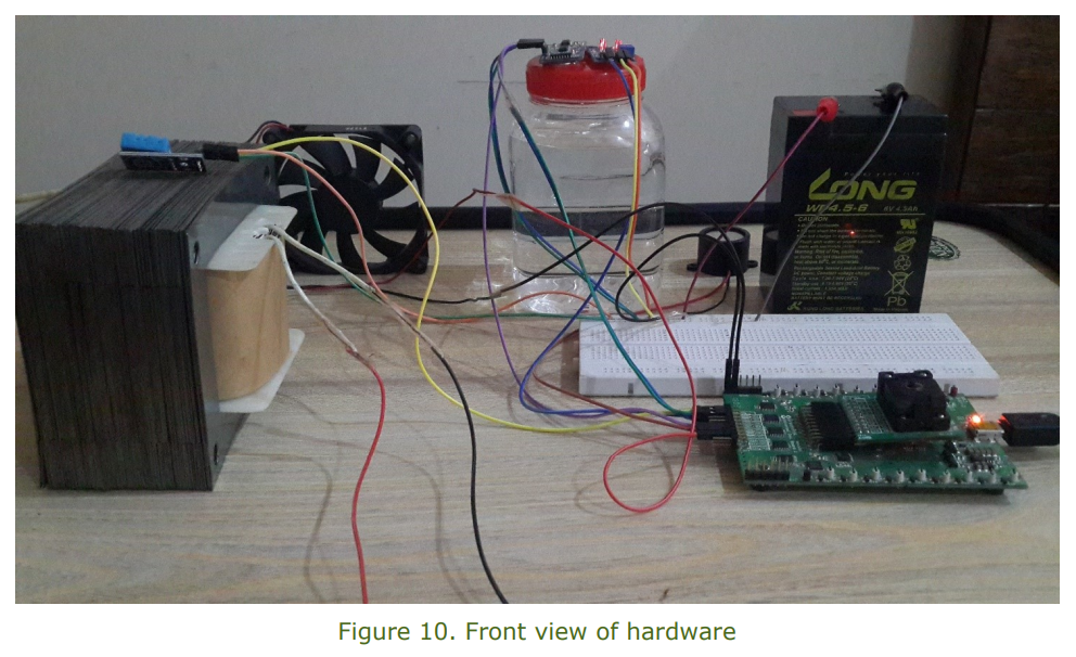
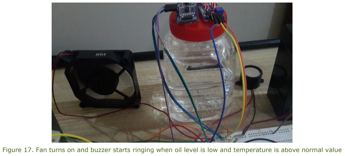
Hardware Pictures
The top view of hardware is shown below.
The front view of hardware is shown below.
Conclusion
In this project, the ambient condition monitoring of a transformer was proposed using the SLG46620V GreenPAK IC as the main controlling element. The small-sized IC performed the monitoring with great accuracy. The GreenPAK IC allowed us to integrate different discrete components into a very small area. This GreenPAK design will improve the sustainability and security of the transformer.