Find out how to design and develop an occupancy-based air quality control system using GreenPAK SLG46140.
Below we described steps needed to understand how the solution has been programmed to create an air quality control system. However, if you just want to get the result of programming, download GreenPAK™ software to view the already completed GreenPAK Design File. Plug the GreenPAK Development Kit to your computer and hit the program to design the solution.
Introduction
The aim of this project is to design and develop an occupancy-based air quality control system using GreenPAK SLG46140V configurable mixed-signal integrated circuit. The system uses Sharp’s GP2Y1010AU0F optical dust sensor to detect the presence of airborne particles and a PIR motion sensor to detect occupancy of the space where the system is installed. A red LED is used to indicate that the air in the room is contaminated while a green LED is used to indicate that the air in the room is clean. This automation system helps to cut electricity consumption by activating an air cleaning mechanism only when there are airborne particles and the space is occupied. The occupancy-based air quality control system can be used in offices, homes, and other residential and commercial environments.
Passive Infrared (PIR) Motion Sensor
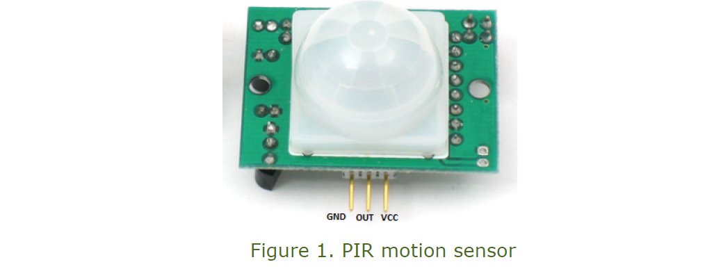
A passive infrared (PIR) sensor is a small, low power, and easy-to-use sensor that is widely used in gadgets and appliances to detect presence or humans or animals. Motion sensors are common in residential, commercial, and industrial settings to detect if a space is occupied or not.
The PIR motion sensor is based on a pyroelectric sensor which detects levels of infrared radiated by a body. The sensor has a Fresnel lens that condenses light to provide the sensor with a larger detection area. The PIR sensor outputs a digital HIGH when a warm body such as a human or an animal passes within it sensing area.
The sensor has three pins: one pin for power (VCC), one for output (OUT), and a ground pin (GND). It can be supplied with a 3-5V DC input. For this project, a 5V input was applied to the VCC pin of the sensor.
GP2Y1010AU0F Optical Dust Sensor
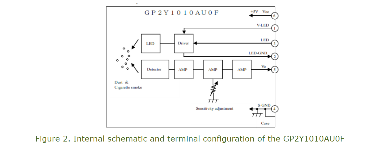
The GP2Y1010AU0F is an optical dust sensing system that is capable of detecting a wide range of airborne particles including fine dust and smoke particles. This sensor is commonly used in many home and industrial appliances including air purifiers, air monitors, and air conditioners. It comes in a compact package that measures 46.0 × 30.0 × 17.6 mm. In addition, the GP2Y1010AU0F is a low current device that draws a maximum of 20mA.
To detect airborne particles, the GP2Y1010AU0F uses an infrared emitting diode and a phototransistor. These two are arranged diagonally in such a way to allow the device to detect reflected light of airborne particles. This compact sensor is capable of detecting fine airborne particles such as those from cigarette smoke. The internal schematic of the GP2Y1010AU0F is as shown in Figure 2.
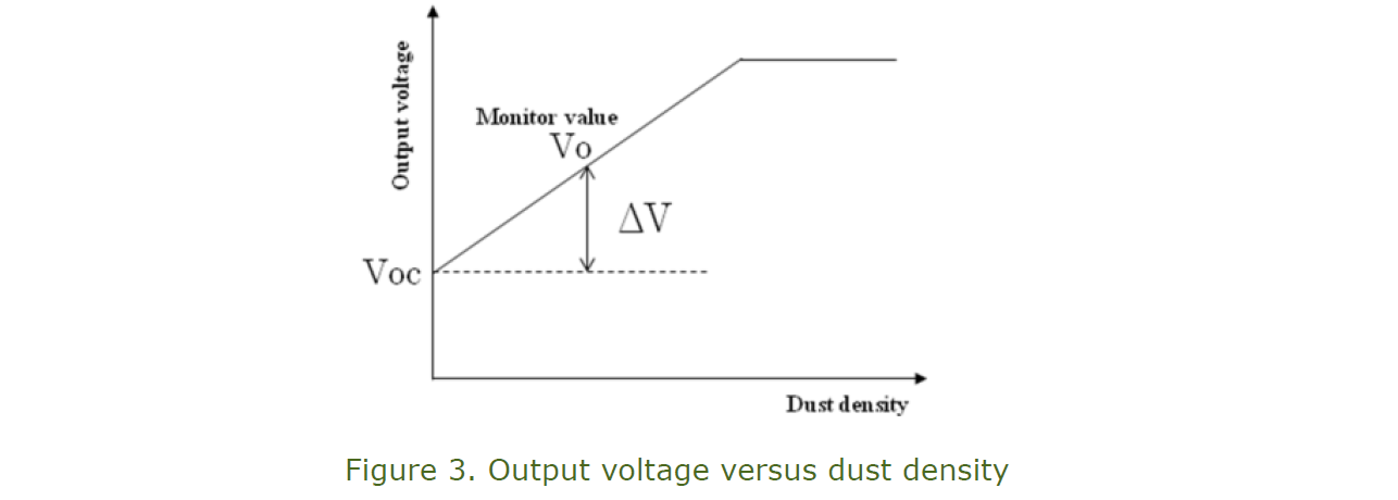
The relationship between the output voltage of the GP2Y1010AU0F and the dust density is as shown in Figure 4. This sensor outputs a voltage even when the dust density is 0 mg/m3. This output at no dust conditions (0 mg/m3) is caused by stray light. Therefore, the output of the GP2Y1010AU0F dust sensor (Vo) is a sum of output voltage when there is no dust (Voc) and output voltage proportional to the amount of dust in the room (ΔV). Voc increases with an increase in the amount of dust that is attached within the dust sensor.
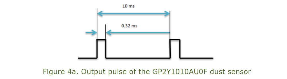
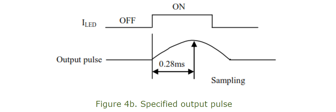
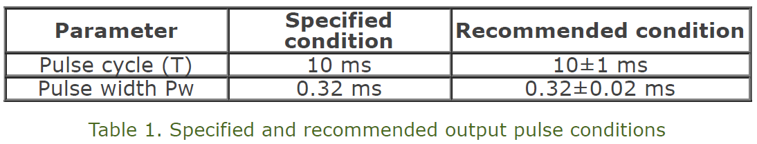
To obtain accurate results, the input applied to the LED terminal should be as specified by the manufacturer. Failing to provide the specified electro-optical conditions can considerably affect the output. When the specified conditions cannot be met, the recommended conditions can be used. Table 1 shows the specified and recommended conditions while Figure 4a shows the expected output pulse. According to the product datasheet, the specified output value is obtained at 0.28ms. The specified output pulse is as shown in Figure 4b.
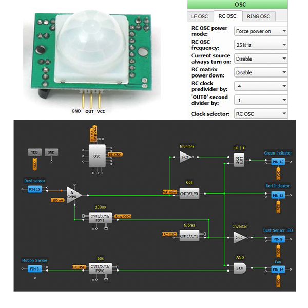
Description of the GreenPAK Design
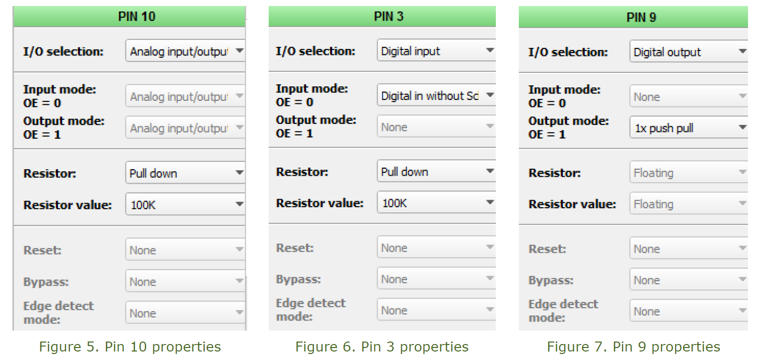
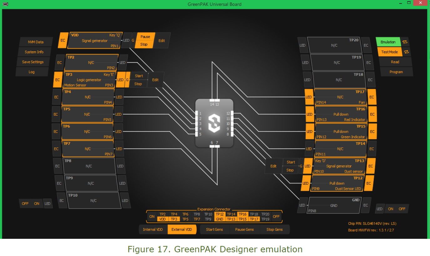
We used a GreenPAK SLG46140V to implement the occupancy-based air quality control system. Pin 10 was configured as an analog input/output while Pin 3 was configured as a digital input. The analog output from the dust sensor was fed to the SLG46140V through the analog input Pin 10. The digital output from the motion sensor was fed to the IC through digital input Pin 3. Pin 9, Pin 12, Pin 13, and Pin 14 were configured as digital outputs. The digital output from Pin 9 was used to drive the LED of the dust sensor. Pin 12 was connected to a Green LED that turned on when the concentration of dust particles in the room is below the reference value. Pin 13 was connected to a Red LED that turned on when the concentration of dust particles in the room went above the reference value. The output from Pin 14 was used to drive the air purification system (a dc fan was used for this project).
The properties of the input and output pins are as shown in the following figures:
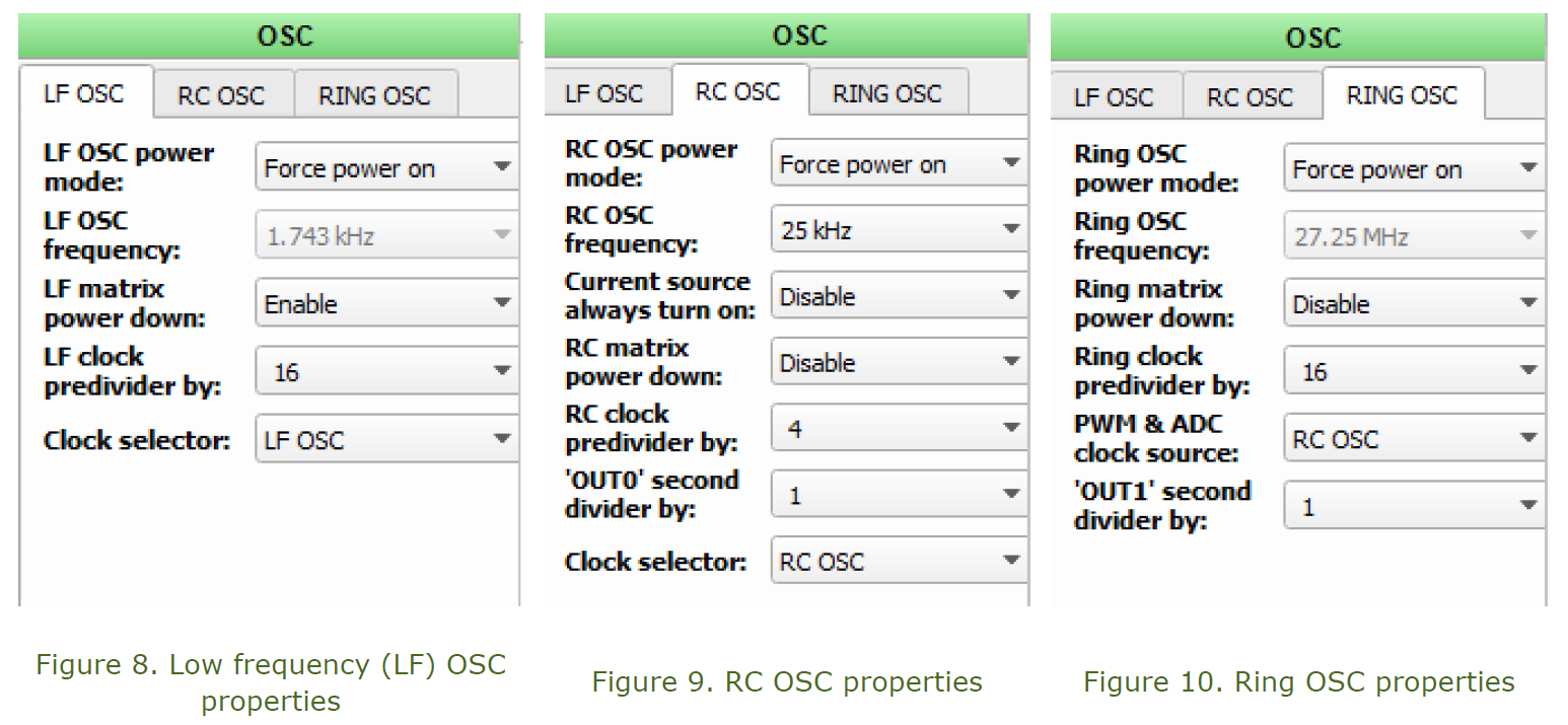
The three internal clock sources of the oscillator block (OSC) were used to provide clock signals to counters and delays. The RC oscillator was used to provide clock signal to the 8-bit CNT1/DLY1 that was configured as a counter. The Ring oscillator was used to provide clock signal to the 8-bit CNT3/DLY3/FSM1 that was configured as a delay. Lastly, the LF oscillator was used to provide clock signal to the 14-bit CNT0/DLY0 and CNT2/DLY2/FSM0 that were configured as delays. The settings of the three internal clock sources are as shown in the following figures:
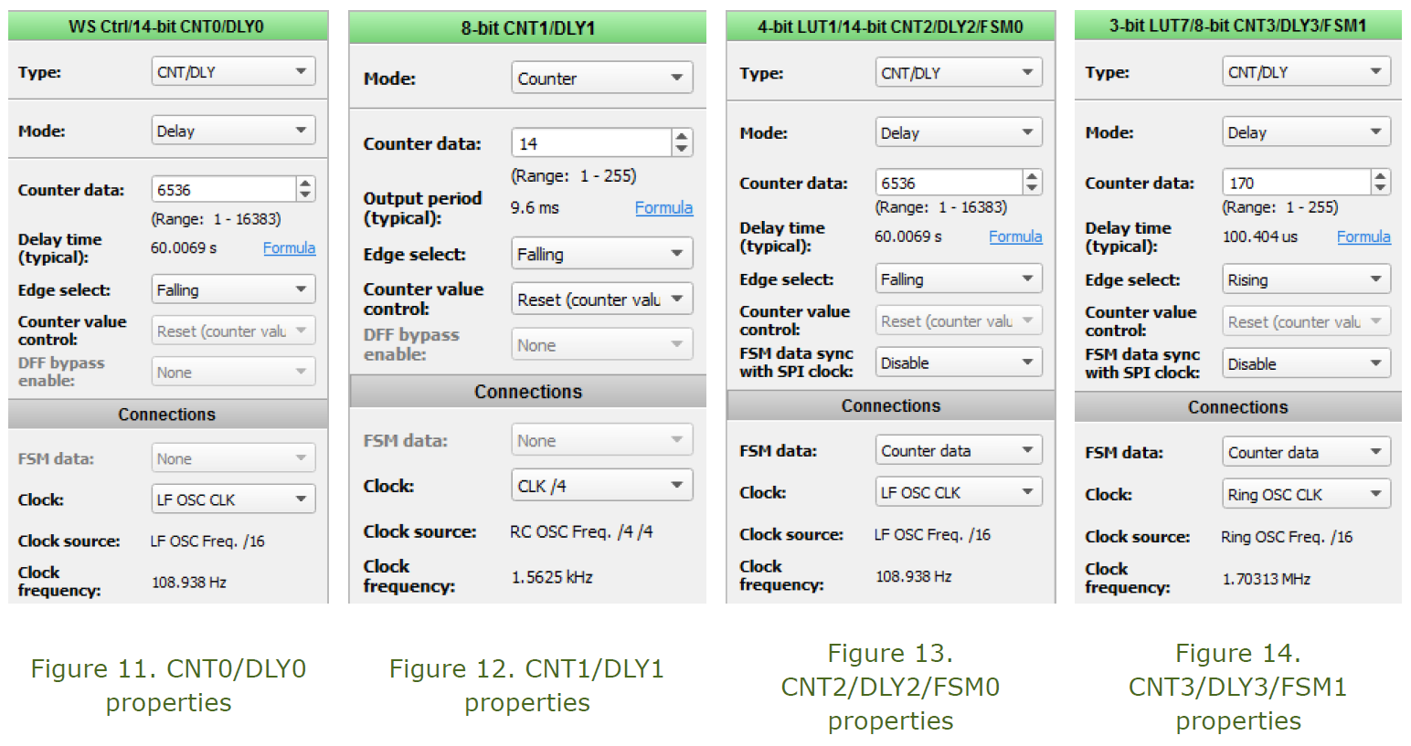
Three Counters/Delays were configured as delays and one as a counter. The 14-bit counters CNT0/DLY0 and CNT2/DLY2/FSM0 were both configured as 60 second falling edge delays. The 8-bit CNT3/DLY3 was set to delay mode to provide a delay time of 100μs. The 8-bit CNT1/DLY1 was set to counter mode with an output period of 9.6ms. This counter was used to provide the pulse specified by the dust sensor’s manufacturer. The properties of the four counters/delays are as shown in the following figures:
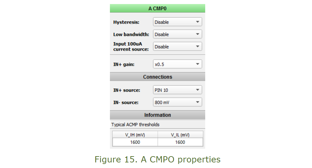
The analog output of the dust sensor was fed to the SLG46140V configurable mixed signal integrated circuit through digital input Pin 10. This pin was connected to a comparator (A CMPO). The comparator halfed the input signal by applying a gain of 0.5 before comparing it with a reference voltage. A reference voltage of 800 mV was used. From the dust sensor’s product datasheet, 1600 mV corresponds to approximately 0.15 mg/m3. The properties of the comparator are as shown in Figure 15:
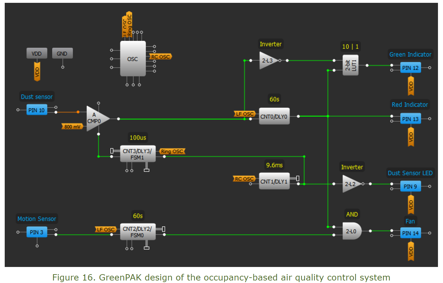
Other components that were used include four LUTs and VDD (PIN 1). The GreenPAK design of the occupancy-based air quality control system is as shown in Figure 16.
The occupancy-based air quality control system controls the air cleaning mechanism and provides the air quality state of the space where it is installed. The Green LED indicates that the number of airborne particles in the room is below the set value while the Red LED indicates that the number of airborne particles is above the set value. The system activates the air purifier only when space is occupied and the number of airborne particles is above the reference value. By activating the air purifier only when the two conditions are met, the system helps to save energy and cut electricity bills.
The dust sensor is used to detect the number of airborne particles in the air while the motion sensor is used to detect the occupancy state of the room. The analog comparator (A CMP0) compares the input with the reference value and outputs a HIGH when the value is exceeded. Otherwise, it outputs a LOW. When the comparator outputs a HIGH, it provides a HIGH to Pin 13. This turns on the Red LED. If the comparator outputs a LOW, the inverter (2-L3) provides a HIGH to Pin 12 and this turns on the Green LED. The 100μs rising edge delay provided by CNT3/DLY3/FSM1 and the 9.6ms falling edge delay provided by CNT1/DLY1 limit the amount of time that the analog comparator (A CMPO) is powered. The two delays help to reduce the amount of power consumed by the comparator. The 60s falling edge delay provided by the CNT0/DLY0 provides a HIGH to the IN1 of the AND gate and Pin 13 (Red LED) for 60 seconds. The 2-bit LUT1 ensures that the two LEDs are not on at the same time.
The 9.6 ms falling edge counter CNT1/DLY1 and the inverter (2-L2) provide Pin19 with a LOW for 0.32ms and a HIGH for 9.6ms. This pulse is used to drive the dust sensor and ensures that Pin 10 is HIGH for 0.32ms and LOW for 9.6ms as specified in the manufacturer’s datasheet. The motion sensor outputs a HIGH when it detects movement within its detection range. The 60 s falling edge delay provides the AND gate with a HIGH for 60 seconds after a falling edge is detected. The AND gate provides a HIGH to Pin 14 when its two inputs are HIGH. This is an indicator that space is occupied and the number of airborne contaminants is above the reference value.
The design was tested under different conditions to verify that it was working as expected. With a low concentration of airborne particles and no motion, Pin 12 (Green LED) was HIGH. With a low concentration of airborne particles and motion within the sensor’s detection range, Pin 12 was HIGH. When a source of the smoke was placed near the sensor and no motion within the sensors detection range, Pin 13 (Red LED) was HIGH. With a source of smoke near the dust sensor and motion within the sensors detection range, Pin 13 (Red LED) was HIGH as well as Pin 14 (Fan).
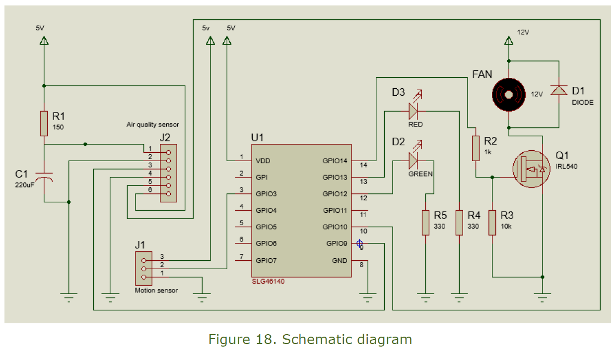
Description of the Schematic Diagram
The schematic diagram of the system is as shown in Figure 17. The SLG46140V, the dust sensor, and the motion sensor were supplied with a 5V DC input. The air-cleaning mechanism (a 12V DC fan) was supplied with a 12V DC input. The GP2Y1010AU0F was connected as shown in the schematic diagram. The values of the resistor R1 and capacitor C1 are specified in the dust sensor’s datasheet. The pins of the dust sensor were connected as specified in Figure 2. Its output was connected to Pin 10 of the SLG46140V while the output of the motion sensor was connected to Pin 3.
The Green and Red LEDs were connected to Pin 12 and Pin 13 of the SLG46140V respectively. Each LED was connected to ground through a 330 ohm resistor. The 5V output provided by the SLG46140V is not enough for a 12V DC fan. A logic-level MOSFET (IRL540) was used to switch the fan on and off from the 5V provided by the IC. The IRL540 is an N-channel MOSFET that offers fast switching and low thermal resistance. The 1N4001 diode was used to eliminate flyback across the DC fan when current is suddenly interrupted.
Applications of the Occupancy-Based Air Control System
Air cleaning systems are widely used in residential, commercial, and industrial environments to remove airborne particles from the air. These air purification systems can consume a lot of electricity if they are allowed to run continuously. The occupancy-based air quality control system monitors presence of humans or animals and air quality and activates the air purifier only when the space is occupied and the concentration of airborne particles is above the set value. The system can be used in residential, commercial, and industrial environments to minimize energy wastage.
Extension of the Occupancy-Based Air Quality Control System
There are many possible extensions that can be done to improve the functionality and performance of this occupancy-based air quality control system. To start with, a fan was used instead of an air purifier. As compared to a fan, an air purifier captures the airborne particles to ensure that the air is clean. Better results can be achieved if an air purifier is used.
The current design does not provide the exact picture of the air quality of the space where the system is installed. Some commercial air quality sensing systems display the concentration of airborne particles. This design lacks this essential feature and it can be improved by using multiple comparators and adding an LCD or LED display.
Considering that most commercial air quality monitoring systems are not designed to detect the presence of humans or animals in the space where they are installed, improvements to this design can make it an unrivaled option. In addition, the SLG46140V is smaller than microcontrollers. This means that this occupancy-based air quality control system is smaller than a microcontroller-based product with the same functionality.
Conclusion
In this project, the SLG46140V configurable mixed-signal integrated circuit was used to build a basic occupancy-based air quality control system. The IC was used to control the sensors, the air quality indicators, and the air purification system. Using the development hardware and the GreenPAK Designer, an air quality control system with more features can be realized.