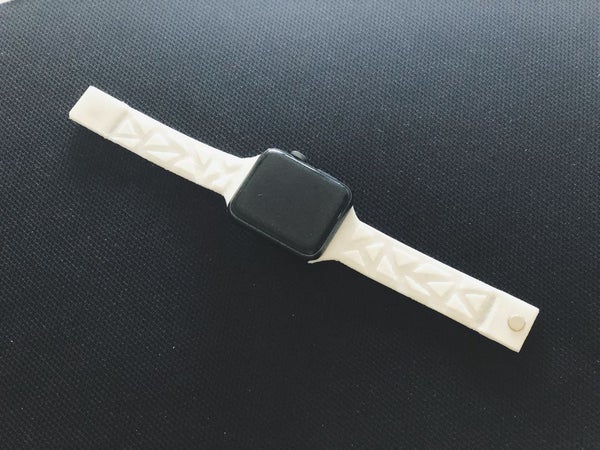
So I made a watch band and print it! It looks nice, fits perfect and is easy in its creation in SelfCAD.
I am big fan of hand watches, but also I want to have something unique. So I made a watch band and print it! It looks nice, fits perfect and is easy in it creation in SelfCAD.
I am big fan of hand watches, but also I want to have something unique. So I made a watch band and print it! It looks nice, fits perfect and is easy in it creation in SelfCAD.
Step 1: Drawing the Base Part
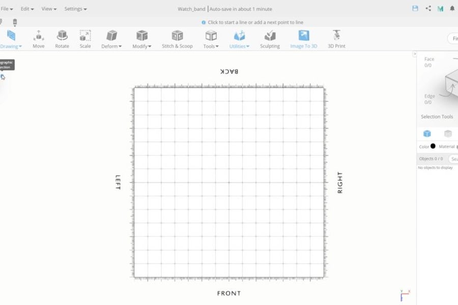
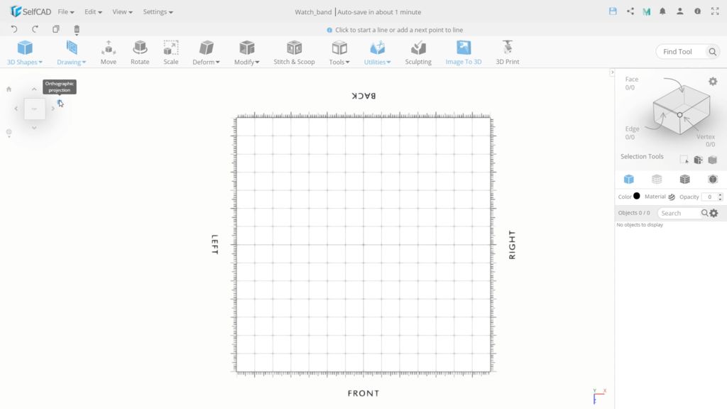
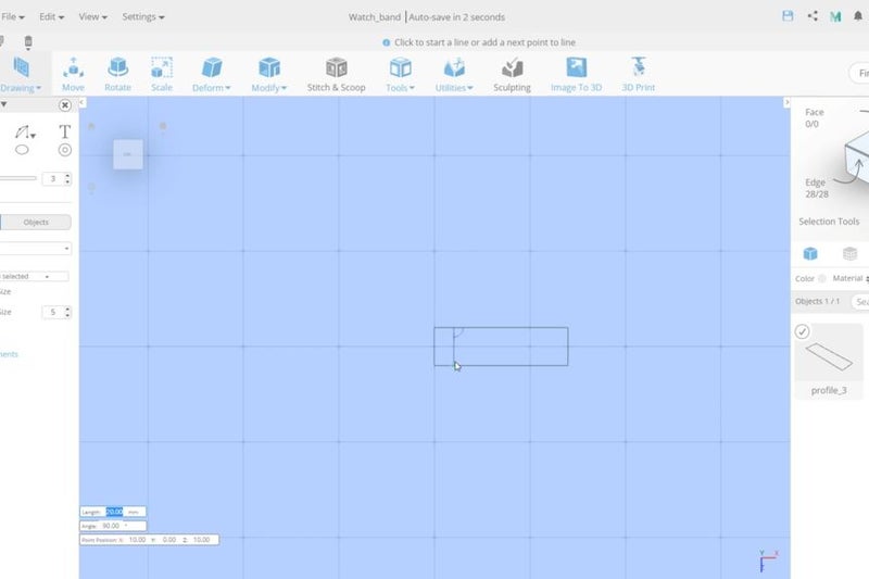
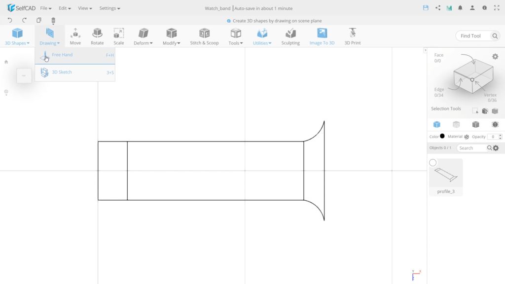
We start by modeling the base, Select the Top view and orthographic projection to turn the workspace into a 2D canvas. Go to the Drawing section and select 3d Sketch In a dropdown find precision settings and switch on minimum step size and set the size to 5. and check the override option. Choose rectangular sketch, and set No. of edges to 7 To draw the base, we will start the first point from the center and move up the second point 2 steps (each one 5). and then move down by the same amount, So the total edge length is 20. then set the width to 72 and so we have a 20x72 rectangle.
We start by modeling the base, Select the Top view and orthographic projection to turn the workspace into a 2D canvas. Go to the Drawing section and select 3d Sketch In a dropdown find precision settings and switch on minimum step size and set the size to 5. and check the override option. Choose rectangular sketch, and set No. of edges to 7 To draw the base, we will start the first point from the center and move up the second point 2 steps (each one 5). and then move down by the same amount, So the total edge length is 20. then set the width to 72 and so we have a 20x72 rectangle.
Step 2: Creating Divider
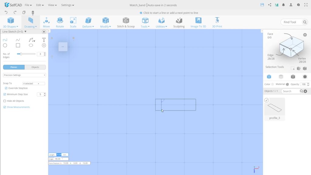
Now let's make a divider, to separate the band from the part with the magnets. Choose line sketch for this, find the top and bottom 2nd points and draw a line between them.
Now let's make a divider, to separate the band from the part with the magnets. Choose line sketch for this, find the top and bottom 2nd points and draw a line between them.
Step 3: Drawing Band Connector
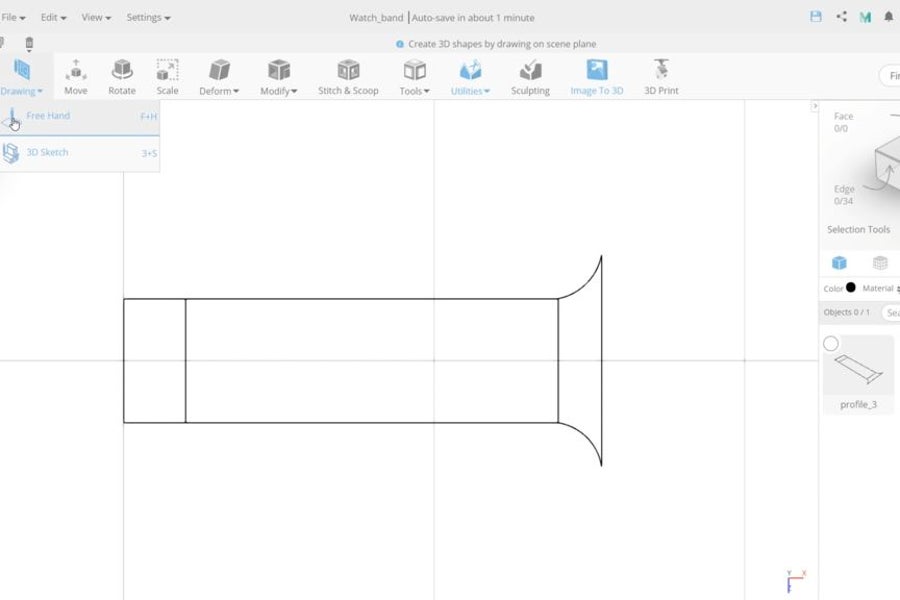
Now let’s combine them all with an arc sketch. Select a 2 Points arc. make sure you have the override step size on, so It ignores the minimum step size when snapping to other points. then draw the arc between the rectangle and the line and Set the angle to 1.5, and repeat the same on the other side.
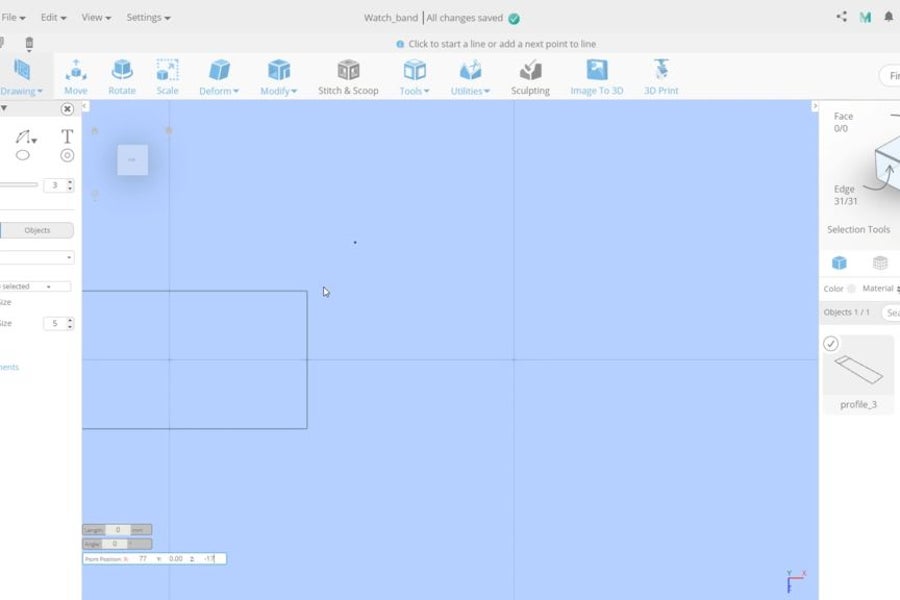
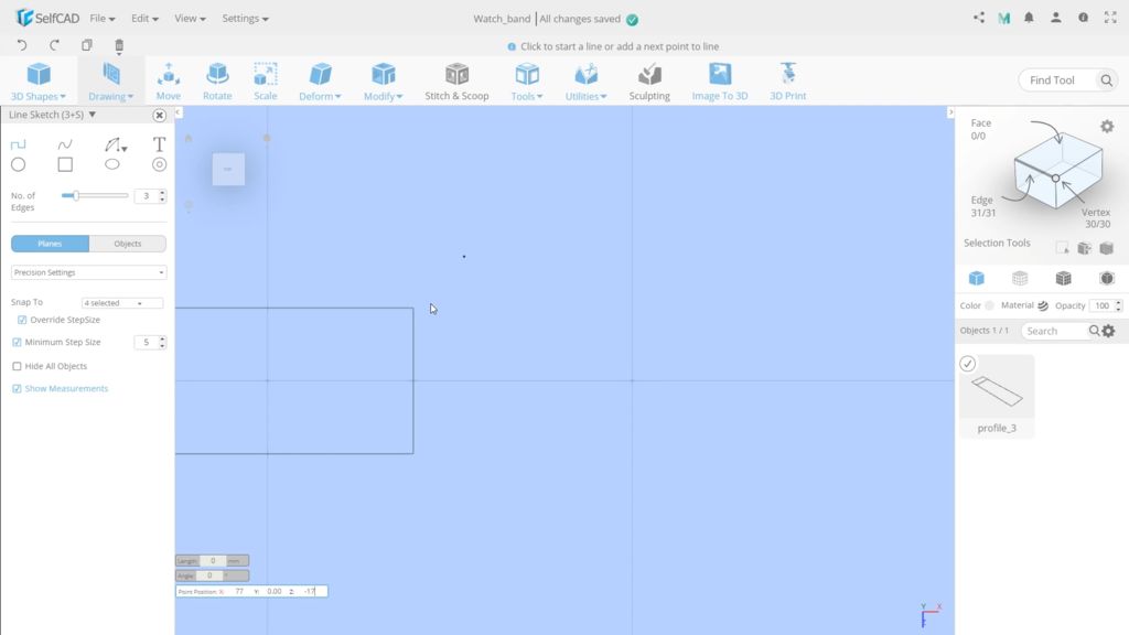
For the next step, Move the camera more to the right and now let’s create the part that will attach the band to the watch. It should have a width of 5 and since our rectangle ends at 72 from the center, draw a line at position 77 on the X-axis and set-17 as the first point on the Z and 17 on the second point to get an edge length of 34, then click escape, not to make unneeded dots.
Now let’s combine them all with an arc sketch. Select a 2 Points arc. make sure you have the override step size on, so It ignores the minimum step size when snapping to other points. then draw the arc between the rectangle and the line and Set the angle to 1.5, and repeat the same on the other side.
Step 4: Creating a Pattern
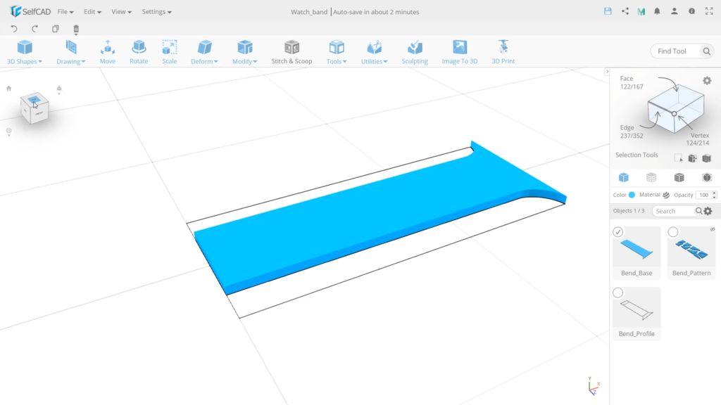
Before we switch back to the perspective projection. We need to make a pattern. I`m doing it right now because it’s easier to draw an appropriate pattern before I convert this profile into a mesh and lose the clear borders. So select the Freehand tool and unhide all objects. Choose the line sketch and draw a pattern you want. I will make it from triangles. Now set the height to 2 and apply. Then turn the perspective projection back on to see our result.
Before we switch back to the perspective projection. We need to make a pattern. I`m doing it right now because it’s easier to draw an appropriate pattern before I convert this profile into a mesh and lose the clear borders. So select the Freehand tool and unhide all objects. Choose the line sketch and draw a pattern you want. I will make it from triangles. Now set the height to 2 and apply. Then turn the perspective projection back on to see our result.
Step 5: Creating the Magnet Section
We need to extrude the part where the magnet is supposed to be it a bit higher. For this; switch to Top view, Turn on face selection, and switch to mesh+ wireframe mode to see the line we draw to divide this object into 2 parts.Then select the smaller part and extrude it by 1.
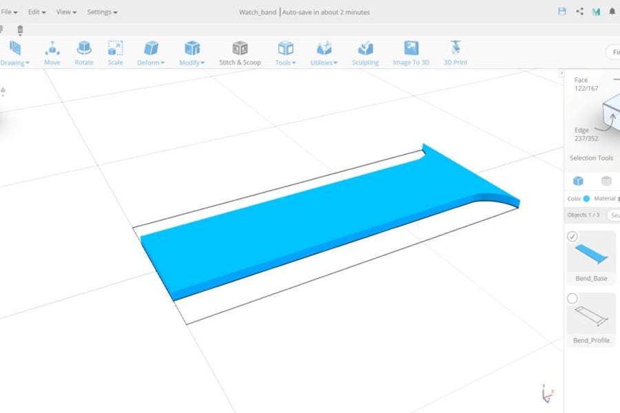
To turn this profile into a 3d object use fill polygons in the Tools section then to add height, use extrusion with the value of 2. I will rename all the objects now. and hide the band pattern, as we won’t work with it now.
We need to extrude the part where the magnet is supposed to be it a bit higher. For this; switch to Top view, Turn on face selection, and switch to mesh+ wireframe mode to see the line we draw to divide this object into 2 parts.Then select the smaller part and extrude it by 1.
Step 6: Creating Magnet Holes Bases
Now we need to move it to the center of this part. However, to position it correctly, we need to do the math and that can take time, so I will show you an interesting tip how you can make such moves much faster. Every object has a pivot point that is used for the objects coordinates. By default, it is in the center but you can position it on some fixed sections of the object, or as in our case, we will position it manually. Open advanced settings and use manual gizmo position and place in the center of this section. You can see that we have 5.03 on X axis and that’s the distance between this part and a center of the grid, so we simply need set the X-axis to 0 and this will place it in the center of the grid and align it with the cylinder. You can see the results by switching to wireframe mode. If we deselect the object the pivot point will reset back in the center of the object and so we now have 33.47 instead of 0 on the x axis.
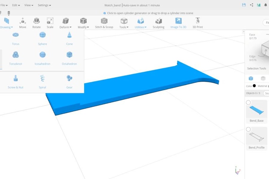
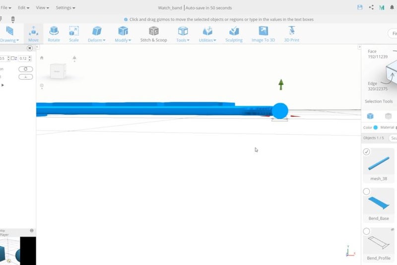
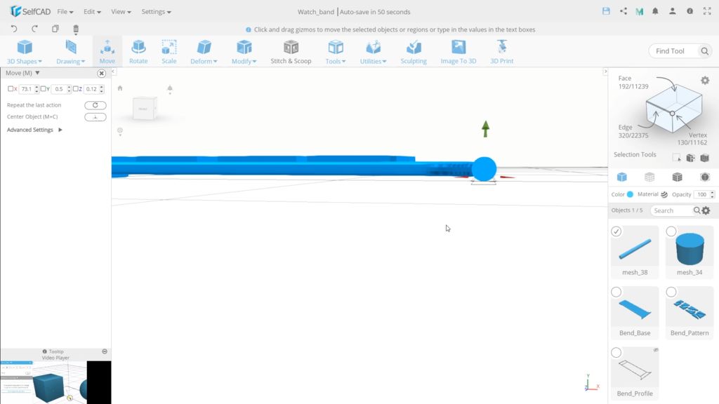
Next, we will create the cylinder that we will use to make a hole to position the magnet. Choose cylinder and set the height to 2.3 and both radiuses to 1.5 and vertical segments to 64 and finalize.
Now we need to move it to the center of this part. However, to position it correctly, we need to do the math and that can take time, so I will show you an interesting tip how you can make such moves much faster. Every object has a pivot point that is used for the objects coordinates. By default, it is in the center but you can position it on some fixed sections of the object, or as in our case, we will position it manually. Open advanced settings and use manual gizmo position and place in the center of this section. You can see that we have 5.03 on X axis and that’s the distance between this part and a center of the grid, so we simply need set the X-axis to 0 and this will place it in the center of the grid and align it with the cylinder. You can see the results by switching to wireframe mode. If we deselect the object the pivot point will reset back in the center of the object and so we now have 33.47 instead of 0 on the x axis.
Step 7: Filling Empty Spaces and Preparing to Creating Different Copies
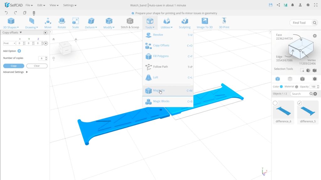
Select the base, turn on the magic fix, Set it to 100, and apply.
Now, if you Rotate it by 180 on the X axis, you will see that we are still missing the backfaces. We can fill it with the fill polygon tool as we did before but I want to show you that we can also fill it with the magic fix tool.
Select the base, turn on the magic fix, Set it to 100, and apply.
Step 8: Attaching the Pattern to the Object
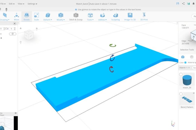
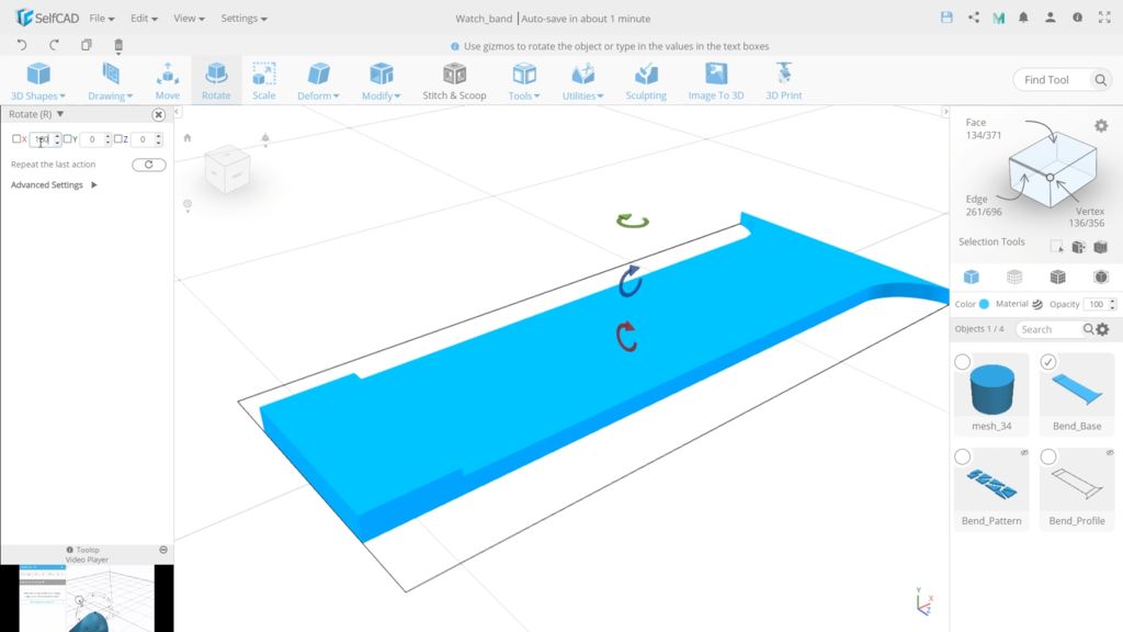
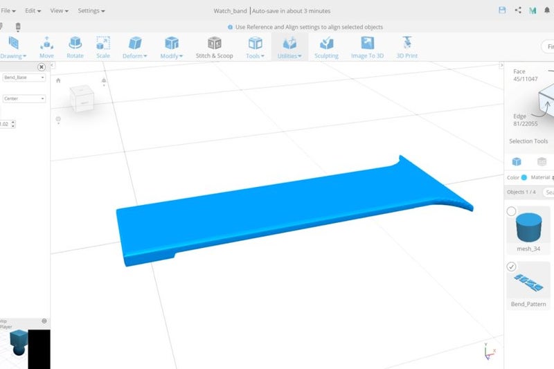
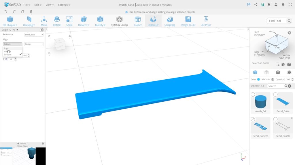
Before we create the final part and make the assembly, I will unhide our pattern. and align it using the Align utility. Set the base as a reference and align it to the top. I will also set a -0.1 offset to the Y-axis to make it bulge in, so that it will solidify correctly on the final step
Before we create the final part and make the assembly, I will unhide our pattern. and align it using the Align utility. Set the base as a reference and align it to the top. I will also set a -0.1 offset to the Y-axis to make it bulge in, so that it will solidify correctly on the final step
Step 9: Creating Connector Between Band and Watch
The last part we need to create is a connector between the band and the watch. Select the cylinder shape and set the height to 34. Top and bottom radiuses to 1.5. Rotate by 90 on X then, to place it correctly on the base, use the align tool, select the right and middle options, to align the object on the middle top. But we need to place it on the right edge horizontally, so Set -0.6 on X-axis and move it to 0.5 on Y-axis
The last part we need to create is a connector between the band and the watch. Select the cylinder shape and set the height to 34. Top and bottom radiuses to 1.5. Rotate by 90 on X then, to place it correctly on the base, use the align tool, select the right and middle options, to align the object on the middle top. But we need to place it on the right edge horizontally, so Set -0.6 on X-axis and move it to 0.5 on Y-axis
Step 10: Merging Together All Parts Except Magnet Hole Base
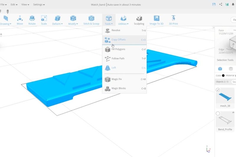
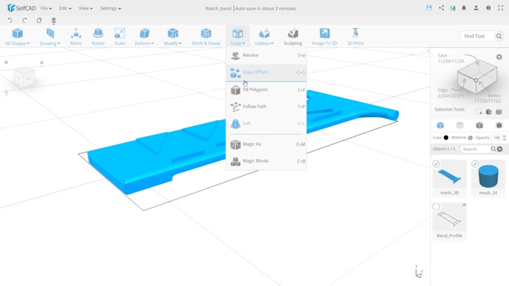
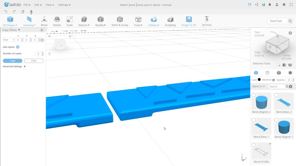
Now, select all objects, except that part that we will use to cut. and merge them. We are almost done but we first need to create to the second band. we can simply make a copy of all the objects and rotate them, or use the mirror tool but I would like to show you, how you can do it using the Pivot tool in the copy offsets. This tool will do it all in one step and is also a very helpful tool for creating many copies in a circular pattern.
Now, select all objects, except that part that we will use to cut. and merge them. We are almost done but we first need to create to the second band. we can simply make a copy of all the objects and rotate them, or use the mirror tool but I would like to show you, how you can do it using the Pivot tool in the copy offsets. This tool will do it all in one step and is also a very helpful tool for creating many copies in a circular pattern.
Step 11: Making Holes for Magnets
Now let’s rename the objects. Then select the bands and position it at 0.1 on the Y-axis, so objects for the magnets will be a little lower. Select the first set and apply Stitch and Scoop with option difference and select the cylinder in the dropdown to cut the cylinder out from the base. For the second band, we need the cut on top, so position the cylinder to 0.75. and repeat the same Stitch and Scoop process.
Now let’s rename the objects. Then select the bands and position it at 0.1 on the Y-axis, so objects for the magnets will be a little lower. Select the first set and apply Stitch and Scoop with option difference and select the cylinder in the dropdown to cut the cylinder out from the base. For the second band, we need the cut on top, so position the cylinder to 0.75. and repeat the same Stitch and Scoop process.
Step 12: Preparing for Print
As we are done, I’m deleting the profile and I’m applying the final magic Fix to make sure the object is ready to print.
As we are done, I’m deleting the profile and I’m applying the final magic Fix to make sure the object is ready to print.
Step 13: Printing and Arranging
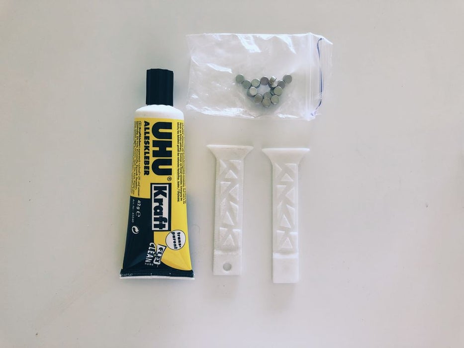
I printed bands with white flexible plastic. It is the most suitable for such model. Printing procecs of an one model tooks me about 1 hour and 40 mins. When bands are printed we need to add magnets. I simply used a glue, but note: the bond strength of a glue should be very hight.
I printed bands with white flexible plastic. It is the most suitable for such model. Printing procecs of an one model tooks me about 1 hour and 40 mins. When bands are printed we need to add magnets. I simply used a glue, but note: the bond strength of a glue should be very hight.