Check out how to control a 3-phase brushless DC motor using a GreenPAK IC.
Brushless DC electric motors (BLDC), also known as electronically commutated motors (ECMs, EC motors) or synchronous DC motors, are synchronous motors powered by DC electricity via an inverter or switching power supply, which produces an AC electric current to drive each phase of the motor via a closed loop controller. The controller provides pulses of current to the motor windings that control the speed and torque of the motor.
The advantages of a brushless motor over a brushed motor are the high power to weight ratio, high speed, and electronic control. Brushless motors find applications in such places as computer peripherals (disk drives, printers), hand-held power tools, and vehicles that range from model aircrafts to automobiles.
This project describes how to control a 3-phase brushless DC motor using a GreenPAK™.
Below we described steps needed to understand how the solution has been programmed to create the DC motor control. However, if you just want to get the result of programming, download GreenPAK Designer software to view the already completed GreenPAK Design file. Plug the GreenPAK Development Kit into your computer and hit the program to design the device.
Construction and Operating Principle
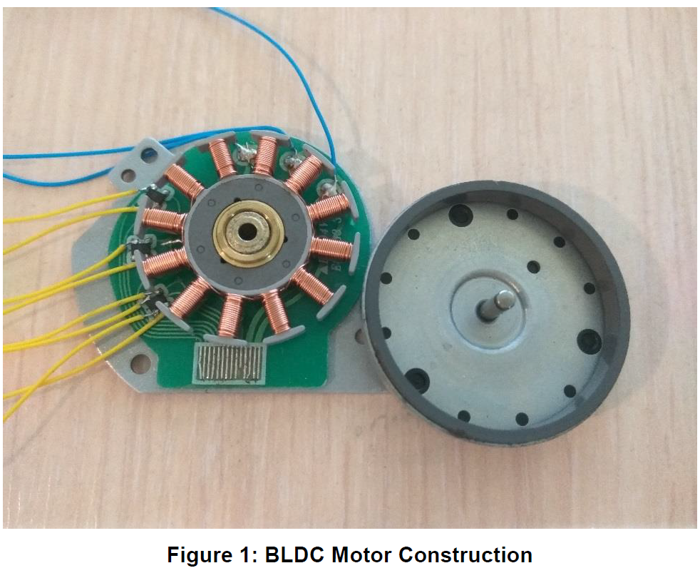
A BLDC motor’s construction and operation are very similar to AC induction motors and brushed DC motors. Like all other motors, BLDC motors also consist of a rotor and a stator (Figure 1).
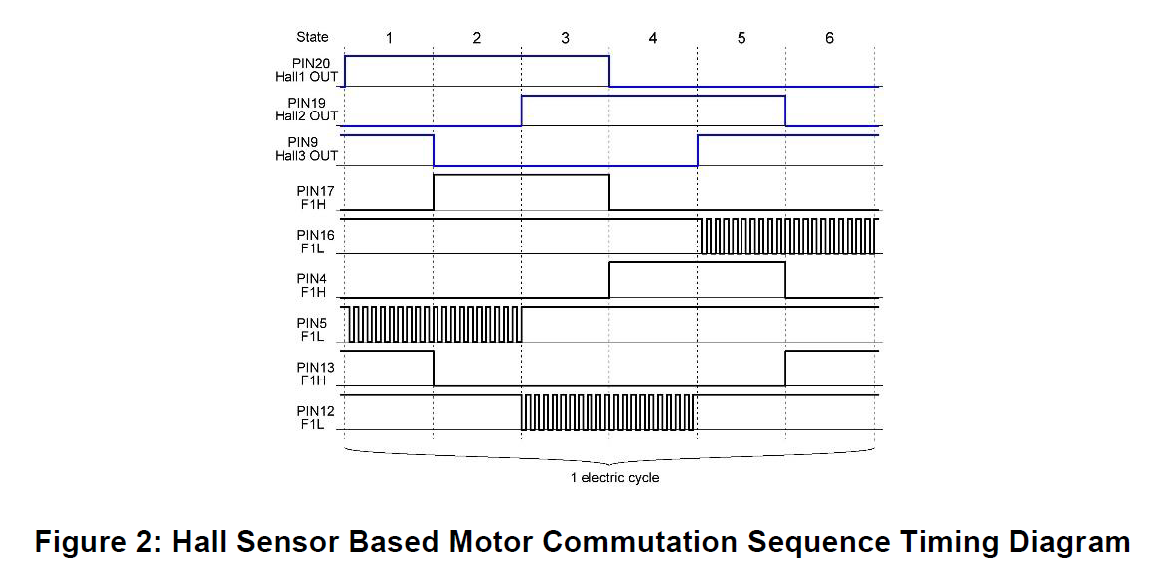
The BLDC motor stator is made from laminated steel stacked up to carry the windings. Windings in a stator can be arranged in two patterns - star pattern (Y) or delta pattern (∆). The major difference between the two patterns is that the Y pattern gives high torque at low RPM and the ∆ pattern gives low torque at low RPM. This is because in the ∆ configuration, half of the voltage is applied across the winding that is not driven, thus increasing losses and, in turn, efficiency and torque. BLDC motors are controlled using electrical cycles. One electrical cycle has 6 states. The Hall sensor-based motor commutation sequence is showed in Figure 2.
The underlying principles for the operation of a BLDC motor are the same as with a brushed DC motor. In the case of a brushed DC motor, feedback is implemented using a mechanical commutator and brushes. In a BLDC motor, feedback is achieved using multiple feedback sensors. The most commonly used sensors are Hall sensors and optical encoders.
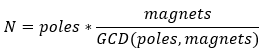
Within a 3-phase BLDC the number of teeth (poles) is a multiple of 3 and the number of magnets is a multiple of 2. Depending upon the number of magnets and teeth each motor has a different number of cogging (i.e. magnetic attractions between rotors and stators) steps per turn. To calculate the number of steps (N) we need to know how many teeth and how many magnets are used in the motor. The motor used in this project has 12 teeth (poles) and 16 magnets.
So, to make 1 turn we need to generate 48 electrical steps.
Design
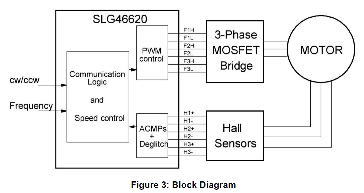
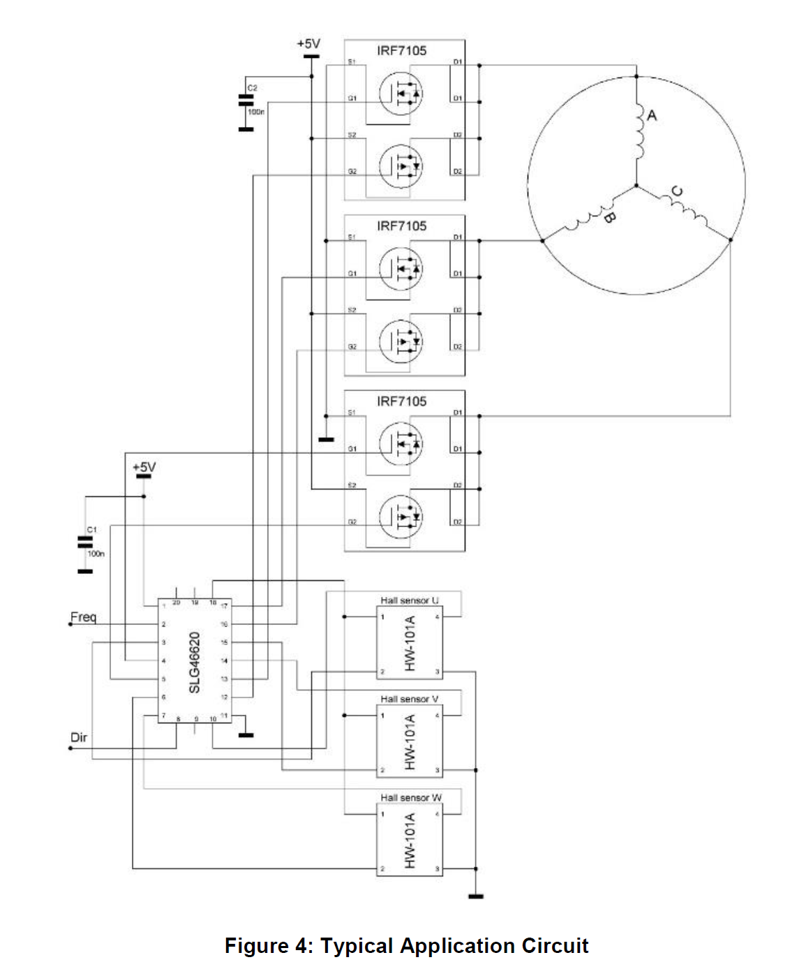
The main block diagram and typical application circuit are shown in Figure 3 and Figure 4 respectively.
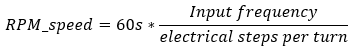
This design has 2 inputs to control motor speed and direction. PIN#8 controls direction; a HIGH level on Pin#8 indicates the motor rotation is clockwise and a LOW level indicates that it’s counterclockwise. PIN#2 is used to control speed via an input frequency. Absence of the frequency signal on this pin will turn off the driver and the motor will stop. Applying frequency to this pin will start the motor during the first 500ms. Using an input frequency allows us to control the motor speed very precisely. To calculate RPM we need to know how many electrical steps a motor contains:
The motor within this application has 48 steps, so at a frequency of 5kHz the motor will run at 6250 RPM.
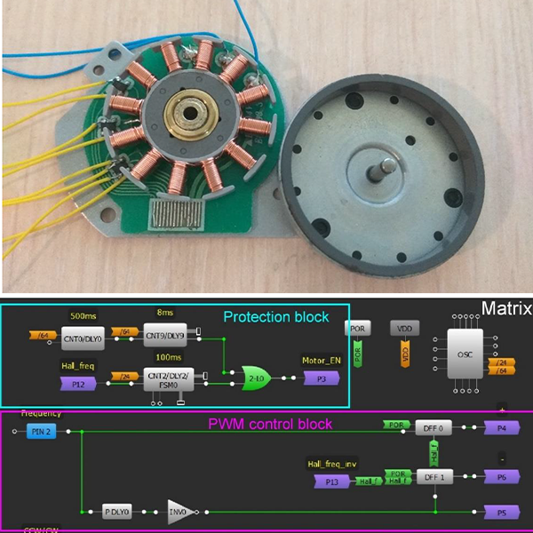
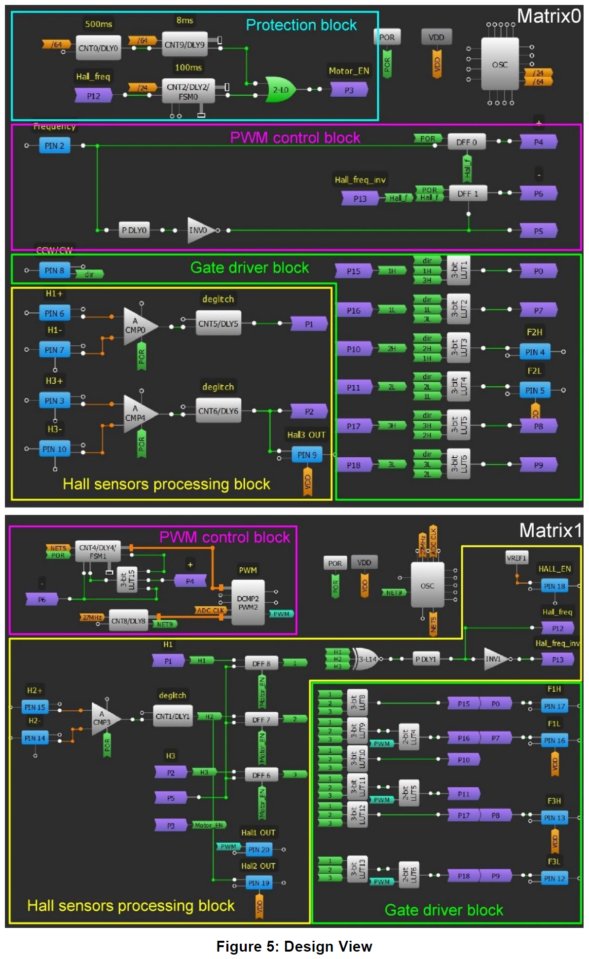
The design can be divided into 4 parts (Figure 5): The Hall sensors’ processing block, a gate driver block, a PWM control or speed control block, and a protection block.
The Hall sensors’ processing block includes ACMPs (ACMP0, ACMP3, ACMP4), deglitch filters (DLY1, DLY5, DLY6) and DFFs (DFF6, DFF7, DFF8). The Hall sensors used in this project have 4 pins; VDD, GND and 2 differential outputs which are connected to IN+ and IN- inputs of the ACMPs. An internal Vref component, set at 1.2 V, is used as a VDD for the Hall sensors. Filtered signals from the ACMPs go into the D inputs of DFFs. The input frequency clocks these DFFs and sets the rotation speed. Signals from these DFFs go to the gate driver and 3-bit LUT14, which is configured as an XNOR. The result is that the output alternates in level each time any Hall sensor changes its polarity. Both edge detectors generate the actual speed frequency (Hall frequency) which is compared with input frequency to generate a PWM signal to control the speed of rotation.
The gate driver block includes 12 3-bit LUTs, which commutate external transistors depending upon the Hall sensors’ feedback. 6 of the LUTs (3-bit LUT8 – 3-bit LUT13) are used for the CW direction and another 6 (3-bit LUT1 – 3-bit LUT6) are used for switching to the CCW direction. This block also includes 3 2-bit LUTs (2-bit LUT4, 2-bit LUT5 and 2-bit LUT6) to mix signals for PMOS transistors of each phase with a PWM to ensure rotational speed is independent to the load.
The PWM control includes the PWM2 component, counter CNT8, finite-state machine FSM1, 3-bit LUT15, 2 DFFs (DFF0 and DFF1), rising edge detector PDLY0, and inverter INV0. DFF0 and DFF1 together operate as a frequency comparator; DFF0 nQ output goes LOW when the input frequency is higher than the Hall frequency and DFF1 nQ output goes LOW when the input frequency is lower than the Hall frequency. At a LOW level on the “+” input the PWM2 OUT+ output will generate a PWM signal with a duty cycle that ranges from 256/256 down to 1/256. At a LOW level on the “-” input, PWM2 OUT+ will generate PWM with a changing duty cycle from 1/256 up to 256/256. The PWM frequency is ~100 kHz and the IC‘s duty cycle is set to 0% at startup. The motor is stopped until the input frequency to PIN2 is applied. After applying a frequency to PIN2, DFF0 nQ output will go LOW and PWM will increase the duty cycle from 0 to 99.6%. The motor will continue to spin until the Hall sensors exceed the input frequency. At this point the DFF0 nQ output will go HIGH and the DFF1 nQ output will go LOW. This inversion causes the PWM duty cycle to decrease to an acceptable value at the immediate VDD and load seen at the motor. This system will constantly work to balance the PWM duty cycle. The functionality of FSM1, CNT8, 3-bit LUT15 and PWM2 are described in more detail in application note AN-1052.
The protection block includes 2 delays (DLY2 and DLY9), counter CNT0, and 2-bit LUT0 configured as an XOR gate. This part of the design is used to protect the motor and external FETs from burning out. If a motor is stuck or cannot start Hall sensors will not be able to give the feedback necessary to turn off the motor. If no feedback is received after 100ms DLY2 output will turn LOW and 2-bit LUT0 turns off the motor. If this occurs CNT0 and DLY9 tries to start the motor every 500ms for a period of 8ms. This period is sufficient to start a motor but is not long enough to cause damage to the motor.
Conclusion
This project describes how to control a 3-phase brushless DC motor using a SLG46620 GreenPAK IC and Hall effect sensors. The SLG46620 also contains other features that can be used for this project. For example, the ADC within the GreenPAK can interpret an input DC voltage and generate a PWM pulse from the value, rather than using an input frequency.
Previously, if a designer wished to control a BLDC motor they would be constrained by both the electrical specs and the features of dedicated off-the-shelf IC solutions. This forced designers to choose a fixed-function and potentially overkill or expensive solution that would often restrict their system’s IO.
The Dialog GreenPAK reverses this design process by bringing configurability back into the designer’s hands. By using this GreenPAK application as a universally-applicable (though also uniquely configurable) 3-phase BLDC motor control scheme, the designer can choose the pinout and external FETs that address the unique electrical specs of their project. Additionally, even considering the external FETs, the Dialog GreenPAK solution is still low cost and small enough that the system design and BOM cost are extremely competitive when compared to dedicated ICs.