Learn about the history of breadboards and when they should and should not be used in circuit design.
Breadboards are a key, reusable piece of hobby equipment in electronics and provide quick circuit construction. However, while breadboards are great, they should not always be used. This article discusses when breadboards should and should not be used in projects.
History of the Breadboard
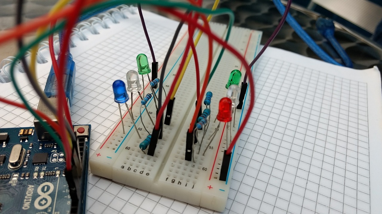
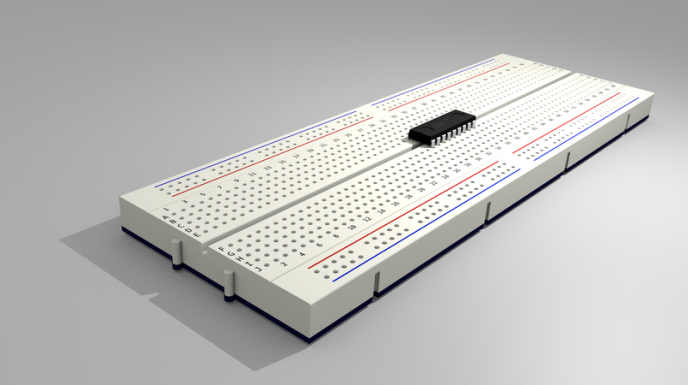
The breadboard is a circuit construction technique that is designed to allow the rapid creation of circuits without the need for soldering or making permanent connections. Leaded components (i.e. through-hole parts), are inserted into holes containing metal grips that gently clamp onto the lead and breadboards almost always have common rows whereby the holes in a row are electrically connected together.
Some breadboards have power rails on either side of the main rows and breadboards are able to house large parts, including DIP 40 ICs. Most breadboards will have clips on the front, back, and sides that allow them to be connected to other breadboards to allow the construction of more complex circuits.
While most engineers use breadboards for more basic circuits some have taken breadboards to the extreme and have built entire working computers complete with sound, a keyboard, and even graphical outputs.
Like most technology, the first available breadboards were very expensive. Thanks to the Chinese market, breadboards are much more affordable. However, caution must be taken when purchasing such parts because cheaper breadboards are often made with inferior materials and the clamps can be loose resulting in faulty circuits.
Although breadboards are incredibly useful in certain situations, it is not uncommon to see hobbyists and engineers alike using breadboards inappropriately. Learning when to use a breadboard or not can potentially save effort, time, and money!
When to Use a Breadboard
Breadboards allow components to be easily inserted and removed—therefore, the word prototyping immediately comes to mind. If an engineer designs a simple module or circuit that they want to test, a breadboard provides a cheap and quick solution (designing a PCB just to test a simple circuit can be overkill and expensive).
When Breadboard Should NOT Be Used
Breadboards, like anything, have their shortcomings. It’s important to remember that they are for the prototyping phase of projects. A breadboard should NEVER be used in a situation where it is intended to be the final product, in an environment where vibration is present, or in cases where safety is concerned (for example, in high voltage projects).
Components on a breadboard are only lightly held in place. Any operator who knocks a wire loose or out of its designated hole by mistake could break the circuit.
Environments involving vibration will easily dislodge wires from the small metal clamps that hold components in place and will therefore fail very quickly.
Any situation that may involve necessary safety features such as an emergency stop or mains voltage controller should never be built using a breadboard. The risk of wire disconnections could result in serious harm with precariously connected safety systems failing or even live voltages being connected to components that need to be touched (such as switches).
Because breadboards use a standard 2.54mm pitch (0.1”) they are very useful for through-hole parts but if a circuit needs surface mount device (SMD) parts, problems could very quickly arise. SMD parts can be soldered to adaptors that convert the SMD outline into a through-hole part but this adds complexity to the final design and uses up an SMD part that would do better on a PCB with all other parts in the circuit.
The most important time to not use a breadboard is in high-frequency scenarios or for circuits that rely on small capacitance values (less than 100pF). Attempting to build high-frequency RF circuits on breadboards is a common mistake made by beginners. In most scenarios the cause of circuit failure is that the capacitance between adjacent rows is somewhat large; as much as 10pF row to row. This can have major effects on high-frequency circuits. A general rule of thumb is to not construct circuits greater than 10MHz in operational frequency on a breadboard. However, microcontrollers operating as fast as 64MHz can be done.
Stripboards Vs. Breadboards
For the projects that include vibration, high frequencies, or safety features, a stripboard is a better option.
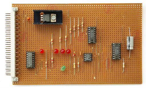
Stripboards offer a way to prototype circuits where breadboards fall short. Image courtesy of Smial [CC BY-SA 2.0]
Using a stripboard requires a similar circuit construction technique to breadboards. However, with stripboards, the components are soldered to the board. While this construction technique could potentially be more problematic, components are better held in place.
If there is an expensive part (such as a microcontroller in a DIP package), a breadboard allows the designer to insert the component, build the circuit, test it, and then easily remove the parts to be reused in a later project, recouping the component cost.
Meanwhile, stripboard circuits use IC sockets whereby ICs are semi-permanently insert and soldered into place. While these ICs can be removed for later use, it is difficult to reuse stripboards.
Breadboards are Great for Designing Simple Circuits
If you want to prototype and test a simple circuit that operates at relatively low frequencies, a breadboard is a good method. Using microcontrollers and complex ICs such as I2C and SPI devices can also be done on breadboards with few problems so long as they operate at relatively slow speeds when interacting with other components on the breadboard (internal frequencies do not matter).
However, when designing a circuit that is susceptible to parasitic capacitances or uses high-frequencies (above 10MHz) then a stripboard or dedicated PCB will be a better choice.


