This project describes the HVPAK configured as a controller for two brushed DC motors
with independent control.
This project describes the HVPAK configured as a controller for two brushed DC motors with independent control.
Introduction
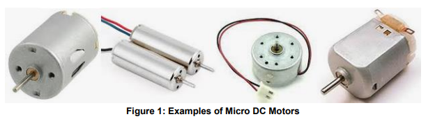
DC electric motors are very widely used. Their popularity is due to their simple control and power supply. DC motors require only two poles, negative and positive, supplied from the source of electromotive force (EMF). When current passes through the DC motor’s rotor coils, the shaft rotates.
If you change the polarity, the direction of rotation will also change. It is also simple to control the velocity of the DC motor. There are many methods to do so—for example, changing the motor’s supply voltage or using pulse-width modulation (PWM) signals.
There is an incredibly wide range of applications for DC motors, even considering just those that are small in size and power consumption. Such motors are used in various tools and auxiliary equipment requiring precise mechanical movements. For example, DC motors are used in various position control systems of optical elements. It is also impossible to imagine modern children's toys without the use of various electric motors, such as models of cars and airplanes, helicopters or ships, and all possible types of robots. DC motors are also often used in Arduino projects. They rotate wheels, propellers, or robot manipulators, and move 3D printer cartridge cradles. It is also worth mentioning the indispensable role of DC motors in office equipment, position control systems for video surveillance systems, in servomotors for smart lock devices, personal and medical care devices, and other consumer electronics.
In order to ensure the correct and error-free use of DC motors in all these applications, it is necessary to meet a certain set of conditions required of a system that directly controls these motors.
This project uses the SLG47105 as an example of such a control system. The controller starts and stops the electric motor, changes the direction of rotation, smoothly adjusts the speed, and protects against emergency situations. Each of these functions can be performed simultaneously for two independent motors, which gives an additional advantage over existing solutions. An example light effect machine demonstrates the simplicity and ease of use of the SLG47105 to control two DC motors simultaneously and independently.
The complete design file can be found here. It was created in the GreenPAK Designer software (a part of the Go Configure™ Software Hub).
Idea and Construction
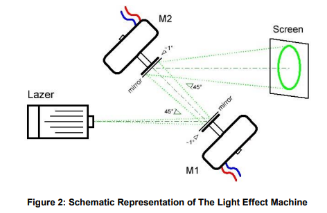
To demonstrate the concept of independent control of two motors, we’ll use the example of a simple light machine which modulates a laser beam via two moving mirrors. The movement of the mirrors, specifically their rotation, is provided by two DC micro motors. Laser beam modulation is achieved by changing the speed and direction of rotation of the mirrors mounted on the shafts of these two motors.
A point that performs two harmonic oscillations in two orthogonal directions forms an ellipse when the periods of both oscillations are equal. In more complex cases, the figures depend on the relation between the periods (frequencies), phases, and amplitudes of both oscillations. To obtain a full-size image of the figure (drawn by a variable laser point), the mirrors must have two directions of incidence of the beam: tangential reflection (at a slight angle of ~ 1°) relative to the plane perpendicular to the motor axis and reflection at an angle of 45 ° relative to the beam. See Figure 2 for an illustration.
If such a modulated beam is projected onto a screen, you can create a wide variety of figures. The simple light effect machine was built in this way.
Design Analysis
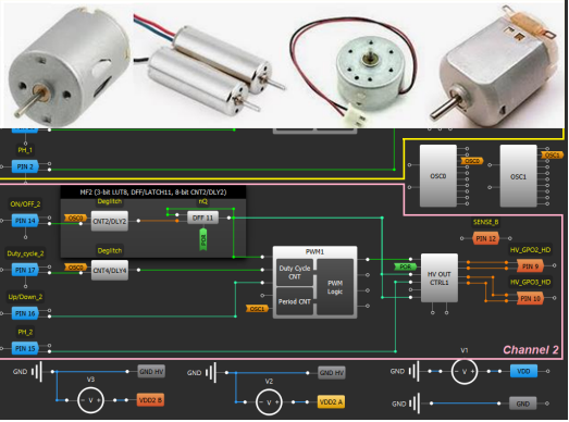
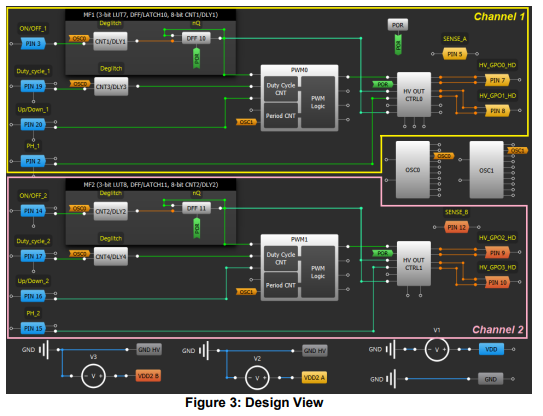
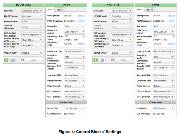
In general, the design is made of two parts with identical functions. Channel 1 controls the M1 motor and Channel 2 controls the M2 motor (Figure 3). To ensure independent motor control, along with the additional possibility to change the direction of rotation, the “Full Bridge” mode was selected in the “HV out mode” option (see the “HV OUT CTRL” settings windows in Figure 4). The direction of rotation of micro motors can be changed with the help of external signals from switches, as seen in the electrical diagram (Figure 5). Speed is controlled by changing the value (from 0% to 100%) of the duty cycle of PWM signals forming the corresponding blocks (Figure 4).
Each motor is switched on and off by a corresponding external button (PIN#3 for Channel 1 and PIN#14 for Channel 2) which changes the state of the corresponding trigger each time it is pressed (DFF10 for Channel 1 and DFF11 for Channel 2). In addition, external buttons (PIN#19, PIN#20 for Channel 1; PIN#17, PIN#16 for Channel 2) are used to change the duty cycle of control PWM signals, that is, change the speed of rotation of the motors. In our case, this method of control was chosen using external signals from buttons and switches. If necessary, the design can be easily modified for control via the I2C interface.
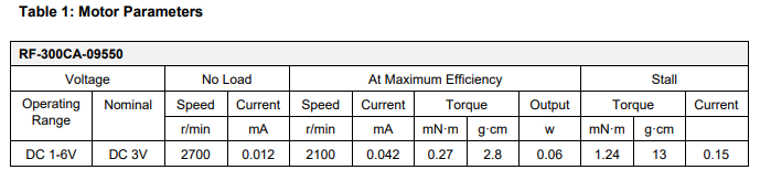
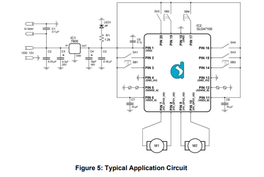
Figure 5 shows a schematic circuit diagram of the light effect machine. The total power supply of the circuit is 6V from the linear voltage stabilizer IC1. To rotate the mirrors, RF-300ca-09550-type DC micro motors are used. Their electrical characteristics are presented in Table 1.
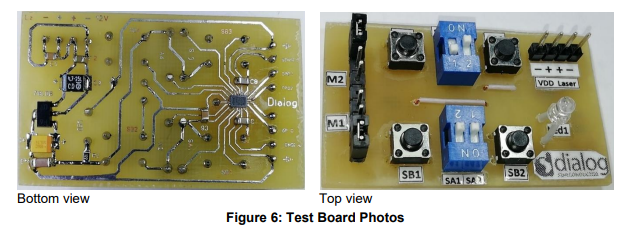
The light effect machine is controlled by four buttons and four switches (two switches and a button per channel). The buttons SB1 and SB3 are used to switch on/off the M1 and M2 motors, respectively (Figure 6). The switch SA1 sets the direction of rotation of the M1 motor, and the switch SA3 sets the direction of rotation of the M2 motor. The direction for changes of the duty cycle of PWM signal (speed increase or decrease) is selected using switches SA2 (motor M1) and SA4 (motor M2). Direct change of speed (change of duty cycle of PWM signal) per unit is carried out by signals from the buttons SB2 (motor M1) and SB4 (motor M2). The LED1 light indicates the power supply status to the entire system.
Test Results
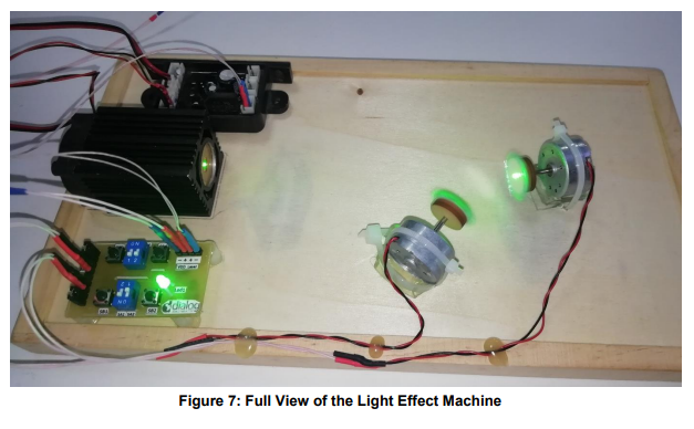
The light effect machine is shown in Figure 7. The following elements are mounted on a wooden base:
■ Two motors rotating the mirrors
■ Green radiation laser and its power supply module
■ The motor control module made with the SLG47105 (shown in Figure 6)
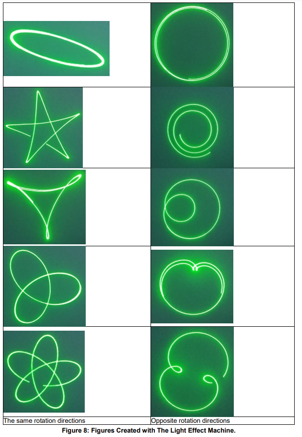
■ In the process of testing, we changed the speed and direction of rotation of the motors, resulting
in figures of different shapes and complexity (Figure 8).
Conclusion
This Application Note describes the HVPAK product SLG47105 configured and used as a driver for two brushed DC motors with independent control. The use of the HVPAK product in such an engineering solution turned out to be a very good choice. Thanks to its functional versatility, easy setup, and a large selection of internal resources, creating a design based on SLG47105 for specific applications is a fairly simple procedure. Low power, small chip size, and low cost are additional advantages when choosing products. You can find an interesting application for the HVPAK on your own, as the full list of HVPAK possibilities is limited only by your imagination.