I will make an IR sensor by using LM358 with a simple step by step process. The activity of the sensor is so simple.
This project and its circuit are some of the most basic and popular sensor modules. In electronics, this Infrared Sensor is analogous to human’s visionary senses which can be used to detect an obstacle which is one of its common applications. In robotics, a group of such modules are used so that a robot can follow a line pattern.
Must Read 100+ Mini Projects
Working Principle
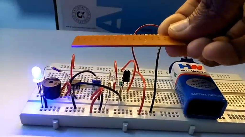
The transmitter part of the sensor project is an Infrared (IR) Led which transmits continuous IR rays to be received by an IR receiver. The output of the receiver varies depending upon its reception of IR rays. Since this variation cannot be analyzed as such, therefore this output can be fed to a comparator. Here operational amplifier (op-amp) of LM 358 is used as a comparator.
When the IR receiver does not receive the signal the potential at the inverting input goes higher than that at the non-inverting input of the comparator (LM 358). Thus the output of the comparator goes low and the LED does not glow. When the IR receiver receives a signal the potential at the inverting input goes low. Thus the output of the comparator (LM 358) goes high and the LED starts glowing. Resistor R1, R2 and R3 are used to ensure that a minimum of 10 mA current passes through the IR LED, photodiode and normal LED, respectively. Resistor VR (preset=10k) is used to adjust the output. Resistor VR1 (preset=10k) is used to set the sensitivity of the circuit. Read more about IR sensor here.