It consists of a fire detector which is released using readily available components having high performance.
Fire hazards have been a major problem for years. Thousands of people die every year due to fire hazards, not to mention the loss of property and permanent damage in health and decrement in lifestyle of the survivors. While large scale industries and buildings have taken measures such as high functioning and sophisticated alarm systems and smoke detectors to warn people of fires, small scale industries and personal homes are still majorly vulnerable to loss of life and serious damage to property due to fire. Security has become an important requisite. Everybody looks for an effective and an efficient way of protecting their possessions. This project is a prototype design that acquires both of the aforementioned qualities. It is a perfect product for small scale industries and homes. This project describes a security system that is applicable anywhere and by anyone. It consists of a fire detector which is released using readily available components having high performance. As soon as the detector will sense fire, a siren will immediately blow and water sprinkler will function to put out the fire and minimize the damage for your project.
BACKGROUND
Each year many buildings, both residential and commercial, are destroyed by fires. About 5 people per 100,000 die annually by fire in Nepal. Bulky systems and technologies have proved to be a disadvantage when it comes to maximum and individual protection in most cases While most commercial and industrial buildings are now being built with water sprinkler systems, many smaller industrial buildings and most of all residences do not have these sprinkler systems. Also, people may not be always aware of a fire. Sometimes, it becomes too late for the fire brigades to put the fire. So, the fire alarm system with siren and water sprinkler is a student made project to serve small scale industries and residential homes. The benefits of embedding fire system with water sprinkle can be summarized as follows:
- This system will help in minimizing loss of lives and property.
- It can be time efficient compared to waiting for the fire ambulance.
- The sound can alert the neighboring houses as well and make them alert as well.
Motivation
An involvement in a project like this for the first time encouraged us at making something simple and beneficial for everyone. We wanted to create something that could help us all in our day to day lives and that would be of immense use in the context of Nepal. So, we thought of all the ways in which we could develop something of greater good for all general people. And as fire has been causing huge damages to life and property many times in our country, we developed the idea of creating this project. It will be of great use in each and every household, as well as industries, factories and every fire-prone areas. Thus, the idea of creating something that could save lives, property and help all people, motivated us in dedicating ourselves to this project.
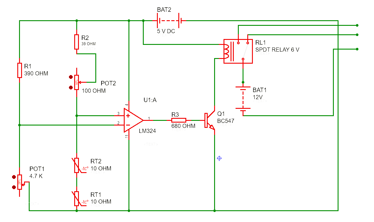
1. Fire Detecting Circuit
fig. Circuit to detect fire
The overall objective of the project is to design and implement simple security system. The device or system is operated in fully autonomous mode. In this mode the device or system operates without any human interaction aside from the start command. The system is designed using two NTC thermistors of 10 ohm are connected in series to the 100 ohm potentiometer which is again connected to the non-inverting terminal of LM-324 op amp so that the potentiometer varies the resistance accordingly. So, the two thermistors are connected to the two potentiometers which vary the resistance. In case of a fire, the resistance of the thermistors decreases as the temperature increases. As the resistance decreases, the output generated from the comparator increases as the voltage increases. This is then passed to the base of BC547 transistor. The transistor has the three terminals performing their respective functions. One coil of relay switch is connected to the collector of the transistor while the other coil is connected to the positive terminal through which voltage is supplied. The emitter is simply grounded. The common point too is connected to the positive terminal of the DC source. The normally close pin remains connected to the common pin which is supplied to a Blue LED to indicate that the system is working properly and to tells people that they are safe. Once the trigger voltage is reached, and then the contact switches from common and normally close to common and normally open. Hence, the final output voltage is supplied to the Red LED, motor and Siren circuit.
2. Circuit For Siren
2.1 Circuit Design
The circuit consists of two 555 timer ICs arranged as shown in the circuit diagram. The first timer IC is connected in a-stable mode to produce pulse of certain frequency. The 4th and 8th pins are shorted and connected to the resistor of 2.2K whose other end is connected to the seventh pin of the timer IC. Sixth and seventh pins are connected to the variable resistor. Sixth and second pins are shorted and connected to the ground of 12v through a capacitor of 47uf. Fifth pin is connected to the ground through a capacitor of 0.01uf. First pin of the IC is connected to the ground.
The output pin of the first IC is connected with a variable resistor of 500K, resistor and Capacitor of 100uF and finally to the control pin i.e. Fifth pin of the second IC. The second IC is also operated in a-stable mode again. 4th and 8th pins are shorted and connected to resistor of 2.2 k ohms whose other end is connected to the seventh pin of the IC. A variable resistor 100K is connected between sixth and seventh pins of the IC. Sixth pin and second pin are shorted and connected to the ground through a capacitor of 0.1uf. First pin is directly connected to the ground of 12v. Output pin of the IC is connected to the speaker through a capacitor of 47uf.
2.2 Working Principle
After the triggering of relay the circuit get the power supply through 12v DC source. When the power is on, the circuit is operated in the a-stable mode. As the voltage is applied to the timer, the capacitor starts charging through the resistors R1 and R2.When it reaches 2/3 of VCC, it is detected by the sixth pin and seventh pin is connected to the ground. Thus capacitor starts discharging, through the RV1 resistor. When voltage of 1/3 VCC is detected it again starts charging, thus this process continuously produces the pulse of certain frequency. This is applied to the second timer through its control pin. Thus the frequency of the second timer is modulated and is applied to the speaker through a capacitor. The external RC circuit decides the time delay with which the waveform should be produced. Hence one can hear the sound like fire brigade.