Tinkering around with Arduino is nice and fun but 32-bit blazing-fast microcontrollers are just another world!
Tinkering around with Arduino is nice and fun but, after a while, you get to a point where the need for more low-level and flexible control is needed, and that is a great time to get away from the high-level Caveats that Arduino Environment provides and to the real practical programming application-based environments, for example, AVR and ARM Cortex-M.
Why STM32?
STM32 is the family of microcontrollers by ST-Microelectronics, these microcontrollers are 32-Bit and the amazingly priced, some even cheaper than 8-Bit AVRs.
32-Bit microcontrollers are nice and all but the real game-changer is the speed of execution of your program and the amount of flexibility microcontroller provides in terms of native hardware supported protocols such as 12C, SPI, CAN, I2S, UART and much more.
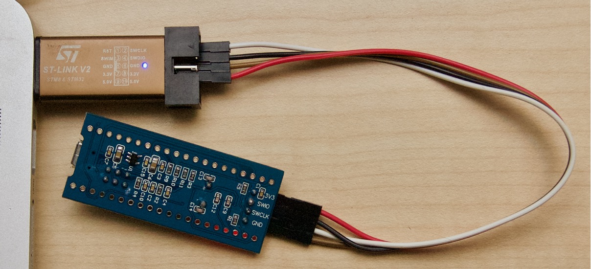
The particular Development Board that we will use in this project is the "Blue Pill", a development board that has STM32F103 running at 72Mhz! and it costs less than 2$ shipped!
You will also need some Jumper Wires and an ST-Link for programming the board.
The CUBE IDE
You need to go to STM's website, provide email and name to download this free IDE, the link to download comes on to email, click it, download it, extract it, install it.
Installation of the IDE is a pretty straight forward process if you have little to no experience in installing software on your Operating System of Choice.
Setting up the Environment
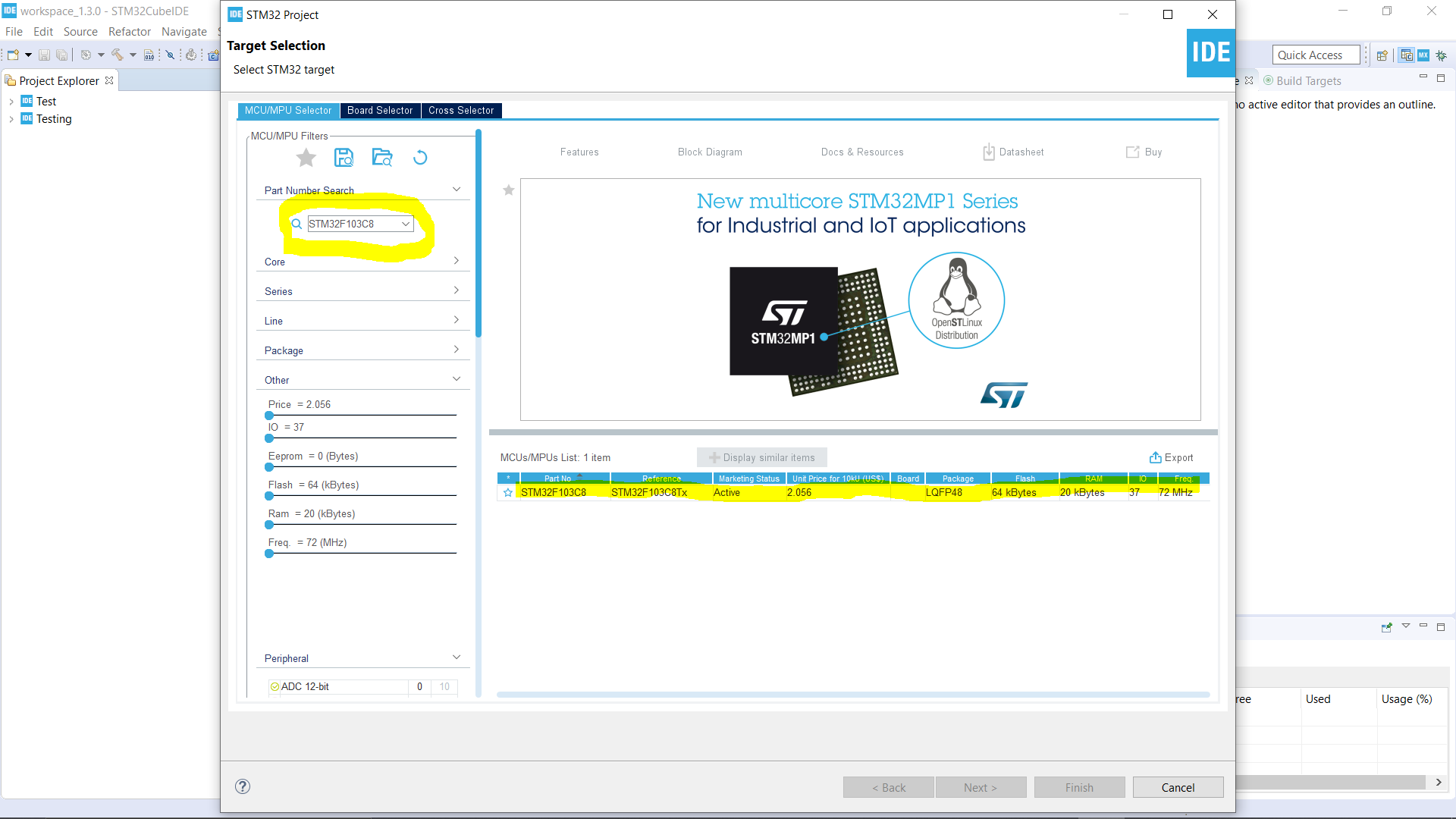
Open the IDE and click on Start a New STM32 Project, then on the Left-hand Side of the IDE you will see a search bar which is a Part Number Search, Type STM32F103C8 and you will have one part appear on the right, select it and click next.
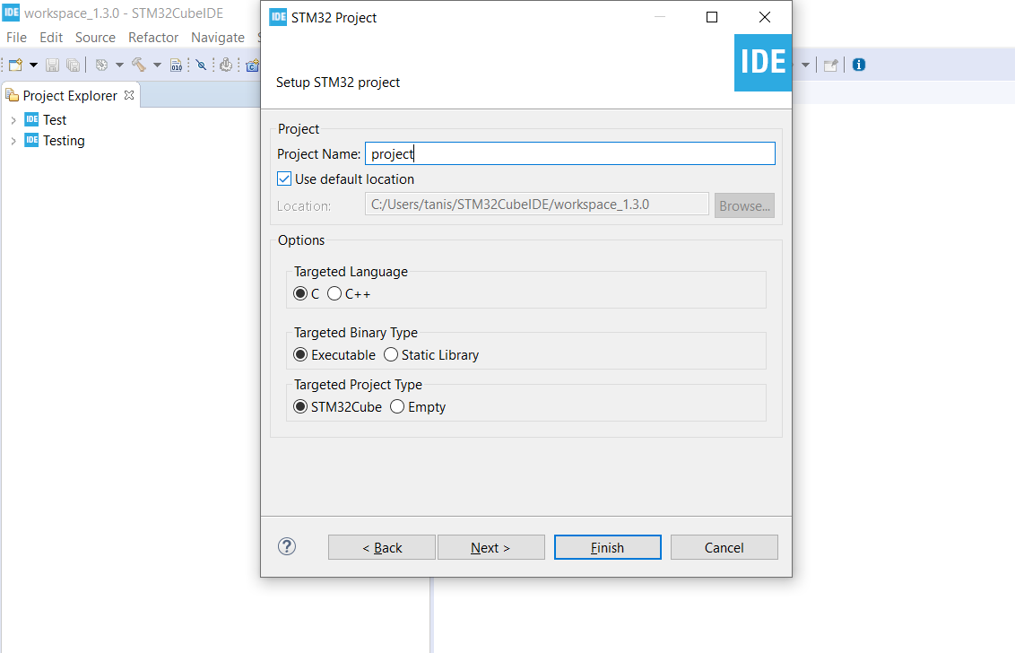
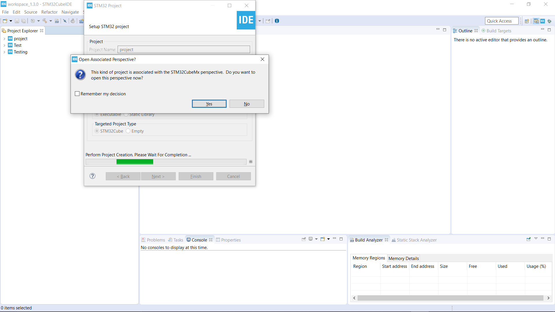
Then Create the project and name it, after this, you will get a pop up saying, "Open Associated Perspective", click on yes, then the files related to our development environment will be installed.
After the download and unzip finishes, we need to do a regular set up specific to our development board.
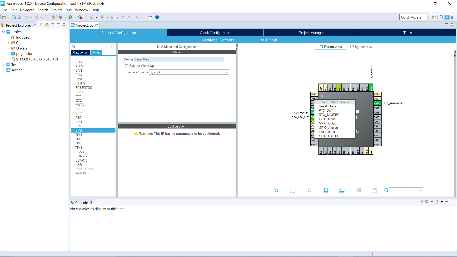
You will see a menu which contains a pinout and configuration tab and inside it, you will see a vertical menu with two tabs, Category, and A-Z, click on A-Z and select RCC, inside it from the High-Speed Clock Dropdown Menu, Select "Crystal/Ceramic Resonator", Disable the Low-Speed Clock.
Now come to the SYS settings, change the Debug to Serial Wire.
Now on the right-hand side, you will see the diagrammatic representation of pinout of the Microcontroller Chip we are using, Click on PC13, from the appeared list select or assign it to "GPIO_Output"
Now, click on the Clock Configuration tab, in which under the PLL Source Mux, HSI is selected by default, turn the tick selection to HSE and in the HCLK instead of "16" write "72". Under the System Clock Mux select PLLCLK.
Finally Coding
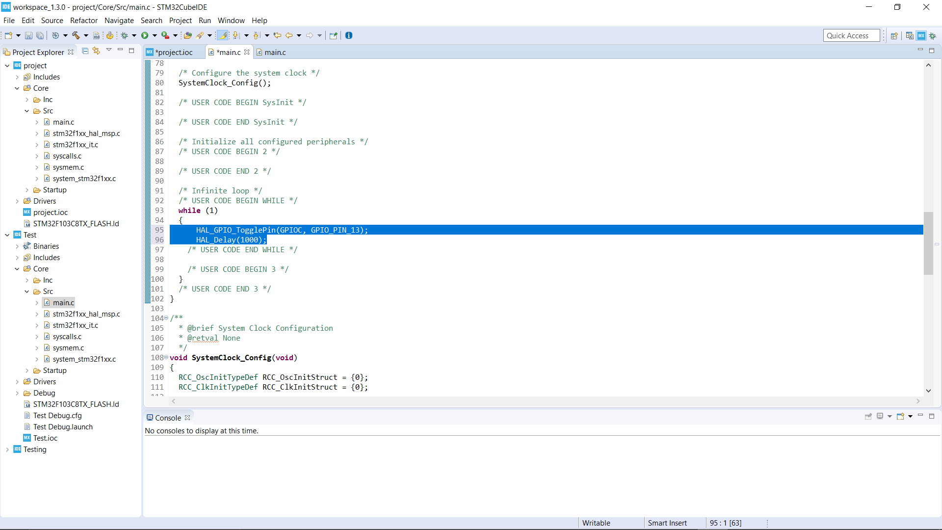
The left-most vertical column expands Core->SRC then you will see the main.c, double click on it, you will see a lot of default code the IDE writes it all ready for you.
But we are interested in the continuous loop, the "while 1" loop can be found under the same main.c, here write the following code, and IMPORTANT: save and generate the code by building the project.
HAL_GPIO_TogglePin(GPIOC, GPIO_PIN_13);
 HAL_Delay(2000);
Build
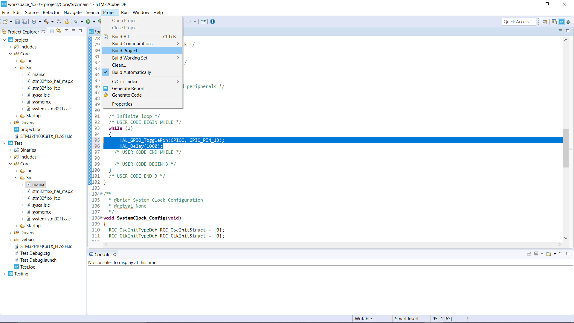
Go to the Project->Build Project and in the console window you should see something like this
17:19:35 Build Finished. 0 errors, 0 warnings. (took 1s.612ms)
Debug Setup
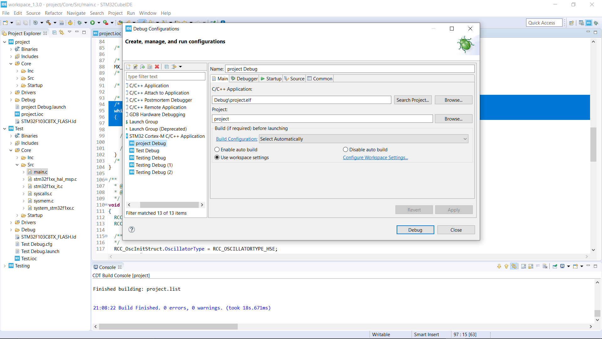
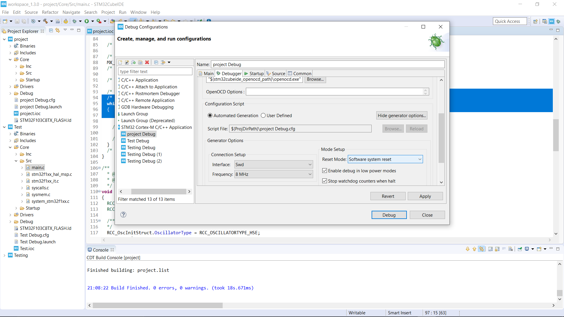
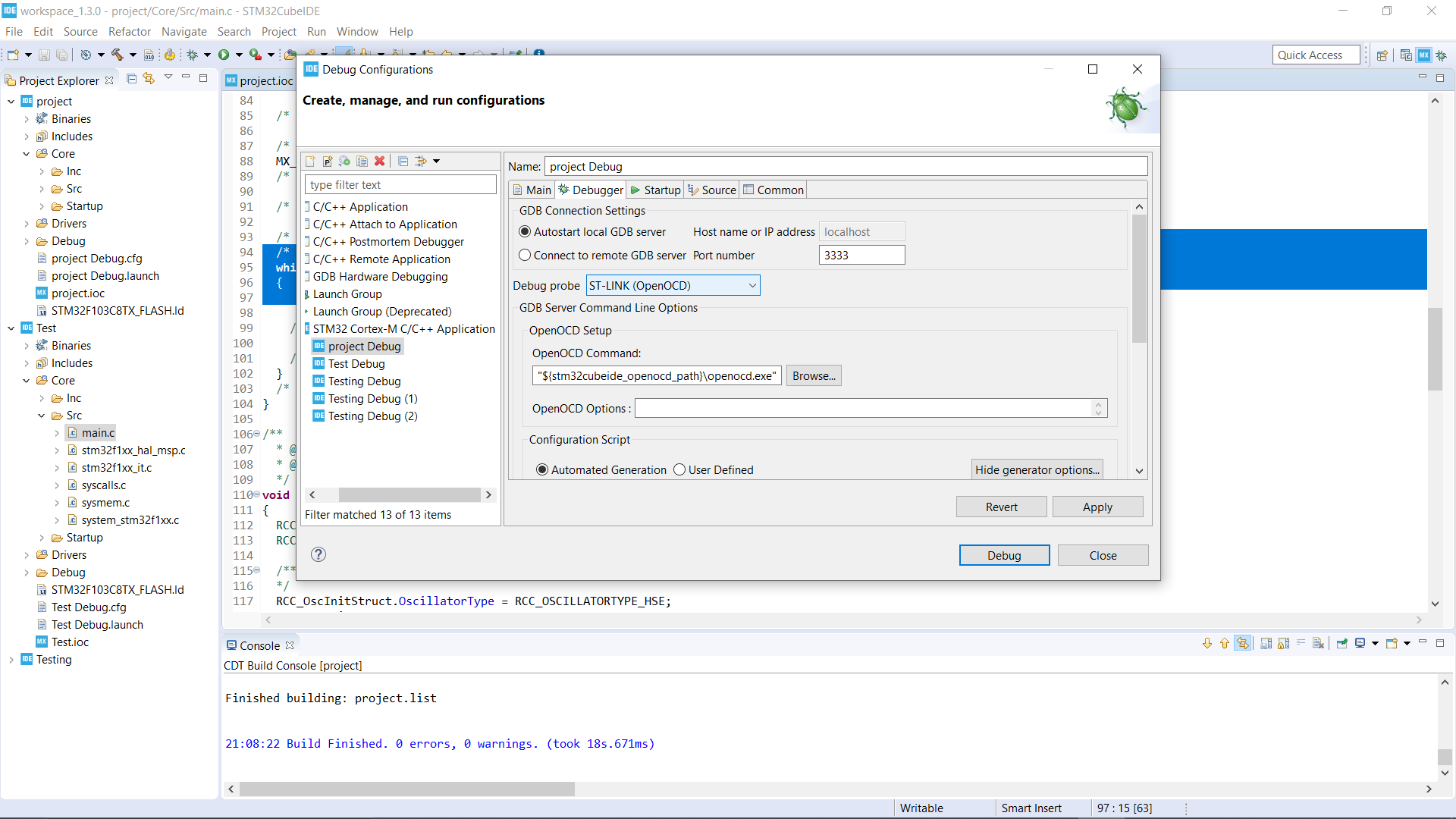
Go to Run->Debug Configurations from the vertical menu in the newly opened window, inside STM32 Cortex M you will see the file name that you are working on, select it, now go to the Debugger tab, in the Debug probe dropdown, select ST-LINK (OpenOCD) and below inside Configuration script click on "Show Generator Options", and in the Reset Mode Dropdown, "Select Software System Reset".
Apply the Settings and close.
Connect STM32 and ST-Link
Connect the ST-Link to STM32 in following Way --
3.3V--3.3V
GND -- GND
SWDIO -- SWDIO
SWCLK -- SWCLK
After making these connections, connect the ST-Link to the USB port your CUBE IDE computer.
RUN!
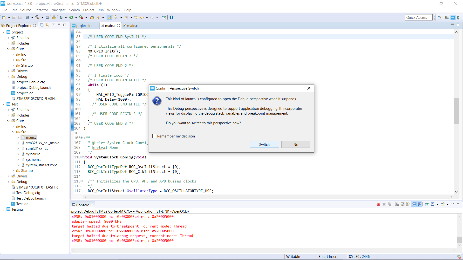
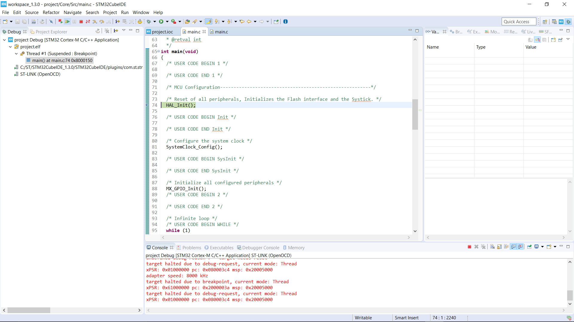
Finally! Click on the tiny debug button, ide will ask you to switch, click Yes and a new window and toolbar will appear, click on resume button and your code will be up and running on the microcontroller!
Thanks for reading!