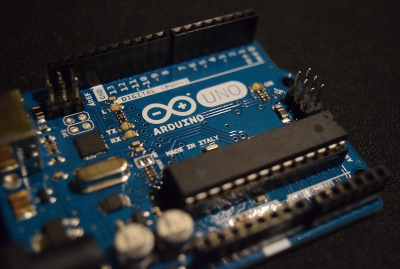
Learn about bit-wise operations for register level programming for Arduino to increase your board’s potential!
To transition away from the more beginner-friendly Arduino IDE framework and begin programming microcontrollers at the register level (also referred to as bare metal), it’s vital to know how to use the C language to manipulate the 1’s and 0’s that make up these spaces in memory. In this article, I’ll introduce how to do exactly that. This article shows how to perform the bitwise operations set, clear, toggle, and read.
Setting a Bit
Setting a bit refers to placing a 1 at a given position in a register, without affecting the other values in the same register. This is done using the bitwise OR operator “ | “. Here’s the truth table for the OR operator:
A | B = Y
When comparing two bits with the OR operator, the output will be 1 if only one of the inputs is 1. If both inputs are the same, 1 or 0, the output will be 0.
To set the bit at position N (remember that C is 0 indexed, so the first position is position 0) in a register to a 1, we can do this:
REGISTER |= (1<<N)
The “1<<N” term is called the mask - it’s used to select the specific bit that we are interested in modifying.
The left shift operator, <<, pushes a number to the left the specified number of times, so 1<<N pushes a 1 to the Nth position of the mask. The register and the mask are ORd ( |= ) to obtain the result.
For example: setting the bit at position 5 in a register called PORTB.
PORTA = 00010001
PORTA |= (1<<5)

PORTA:              00010001
MASK:               00100000
PORTA |= (1<<5):    00110001
The bit at position 5 in the register has been set to 1. The other bits in the number are unchanged - no matter if they were 1 or 0.
Clearing a Bit
Clearing a bit refers to placing a 1 at a given position in a register, without affecting the other values in the same register. This is done using the bitwise AND operator “ & “. Here’s the truth table for the AND operator:
A & B = Y
When comparing two bits with the AND operator, the output will be 1 if both inputs are 1. Otherwise, the output will be 0.
To clear the bit at position N in a register (set it to 0), we can do this:
REGISTER &= ~(1<<N)
Take note of the fact that when clearing a bit, we NOT (~) the mask. The NOT operator inverts every bit in a number - the 1’s become 0’s, the 0’s become 1’s.
For example: clearing the bit at position 2 in a register called PORTB.
PORTB = 00011111
PORTB &= ~(1<<2)

PORTB:               00011111
MASK:              ~(00000100)
MASK:                11111011
PORTB &= ~(1<<2):    00011011
The bit at position 2 in the register has been set to 1. The other bits in the number are unchanged - no matter if they were 1 or 0.
Toggling a Bit
Toggling a bit refers to flipping the value of a bit - if it’s a 0, make it a 1. If it’s a 1, make it a 0. This is done using the bitwise XOR operator “ ^ “. Here’s the truth table for the XOR operator:
A ^ B = Y
For example: toggling the bit at position 5 in a register called PORTC.
PORTC = 00000001
PORTC ^= (1<<6)

PORTC:              00000001
MASK:               01000000
PORTA |= (1<<6):    01000001
The bit at position 6 in the register has been flipped from a 0 to 1. The other bits in the number are unchanged - no matter if they were 1 or 0.
That changed a 0 to 1, but the same operation works to change a 1 to 0.
PORTC = 00100001
PORTC ^= (1<<6)

PORTC:              01000001
MASK:               01000000
PORTA |= (1<<6):    00000001
Reading a Bit
Registers are not only written to, but they are also read from. To read if the value of a certain bit in a register is a 0 or a 1, we mask all of the other bits to a 0 (leaving the desired bit unaltered), and then check the resulting number. If the result is all 0’s, we know that the desired bit was a 0. If the result is anything else, we know that there was a 1 in the desired position.
This explores the concept of bitwise TRUE and FALSE. A false is a 0, and a true is anything greater.
For example: reading the bit at position 7 in register PORTD. We can check the result with an IF statement in the C language.
PORTD = 10000000

if (PORTD & (1<<7) ) {
     return 1;
     else{
          return 0;
         }
     }

PORTD:              10000000
MASK:               10000000
PORTA &= (1<<7):    10000000

The function will return 1, as the result isn’t all 0’s.
Another example: reading the bit at position 0 in register PORTD.
PORTD = 10000000

if (PORTD & (1<<0) ) {
     return 1;
     else{
          return 0;
         }
     }

PORTD:              10000000
MASK:               00000001
PORTA &= (1<<7):    00000000

The function will return 0, as the result is all 0’s.
A microcontroller’s datasheet (or hardware reference document), maps out the registers for all of its peripherals, like GPIO’s, ADC’s, and communication buses. When using a framework like Arduino, a hardware abstraction layer, or any other microcontroller library, the registers are mostly hidden inside of more user-friendly functions. However, knowing how to manipulate registers is essential to understanding the device’s operation, and the key to full control over its features.


