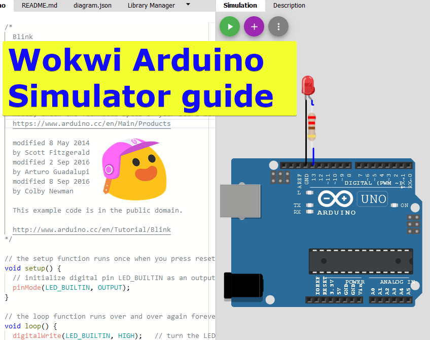
In this article, you will learn how to use Wokwi Arduino Simulator by building Arduino UNO, LED and the Button
In this article, I will show useful tips and steps so that you can start working on your Arduino project simulation on the Wokwi Arduino Simulator
Home links for the Wokwi Simulator
- Home page - https://wokwi.com/
- Documentation - https://docs.wokwi.com
- Wokwi LED element - https://docs.wokwi.com/parts/wokwi-led
- Wokwi Push Button - https://docs.wokwi.com/parts/wokwi-pushbutton
- Facebook group for support and discussions - https://facebook.com/groups/wokwi
- Discord Community - https://wokwi.com/discord
What is Wokwi?
Wokwi is an online simulator that simulates several electronic components as well as Arduino and ESP32 boards. For a full list, refer to the Wokwi Docupedia page. Wokwi Arduino simulator is 100% free - It means, it provides unlimited simulation time as well as all the components available
Let us build the circuit first
For the demo, I will connect an LED and a button to the Arduino UNO. The below image covers all the necessary steps involved in the project building.
- Open an Arduino template project by clicking on the following link
- There will be two windows (Editor window and Simulator window).
- We will head to the simulator window
- Click on the purple PLUS symbol to add the components
- Add an LED and a push-button
- Connect the Anode of the LED to pin number 5 of the UNO
- Connect the button to pin A1 of the Arduino
- connect the cathode of the LED to the GND pin of the Arduino
- finish the connection as shown
Building circuit for the demo project
The finished circuit will look like this. You can drag around the components to make sure it looks good and others can easily understand your circuit.
In the below section, you will find the code
// Blue button has bouncing simulation disabled.

#define BUTTON_PIN A1
#define LED_PIN 5

void setup() {
  pinMode(LED_PIN, OUTPUT);
  pinMode(BUTTON_PIN, INPUT_PULLUP);
}

int lastState = HIGH;
void loop() {
  int value = digitalRead((BUTTON_PIN));
  if (lastState != value) {
    lastState = value;
    if (value == HIGH) {
      digitalWrite(LED_PIN, LOW);
    }
    if (value == LOW) {
      digitalWrite(LED_PIN, HIGH);
    }
  }
}
The project link is given below. You can use this link easily to play with the simulation and tinker with the code.
Link: https://wokwi.com/arduino/projects/321930981708661331
#define BUTTON_PIN A1
#define LED_PIN 5
Above two lines of code defines two constants. LED is connected to pin number 5 and the button is connected to analog pin A1
void setup() {
  pinMode(LED_PIN, OUTPUT);
  pinMode(BUTTON_PIN, INPUT_PULLUP);
}
In this section, you will do all the initialization. You will configure the LED pin as an OUTPUT pin and the Button pin as an INPUT pin.
void loop() {
  int value = digitalRead((BUTTON_PIN));
  if (lastState != value) {
    lastState = value;
    if (value == HIGH) {
      digitalWrite(LED_PIN, LOW);
    }
    if (value == LOW) {
      digitalWrite(LED_PIN, HIGH);
    }
  }
}
In this section of the code, you read the status of the pin to which the button is connected, all the time. If you detect a change in the button state, you will take action. Please feel free to post questions if any.
Summary
In this article, we found how to add new components into the Wokwi Simulation circuit. We also completed the code so that the project can run successfully.