Learn to build supporting circuits to help reduce your Arduino's power consumption in your projects.
In How to Reduce Arduino Power Consumption, we looked at ways to reduce power consumption within the Arduino by changing hardware or modifying code. However, there are also ways to reduce the power consumption of an Arduino by adding some simple external circuits.
In this article, we design some external circuits to control the power flow to our Arduino to help externally regulate the power flow. The circuits presented in this article are to be used and work best when you want to multiply your battery life in any sensor-based Arduino project.
External Timer Circuit
In Arduino-based projects like weather stations, data loggers, or other monitoring systems, it isn’t necessary to power them 24 hours a day. Instead, we can power the project for a few seconds at a chosen time interval. For example, we can power the project for 30 seconds every 5-10 minutes. This would turn the Arduino system completely off for the majority of the time, saving a lot of energy.
In the above-stated situations and projects, an Arduino reads sensor values periodically and stores the readings or transmits them via Wi-fi or Bluetooth and then enters an idle state. Putting the Arduino to sleep for some time can save power consumption but we will see a comparison of the power consumed at the end of this section. For now, know that power consumption by a regulator or other peripherals on the board is very high and consumes most of the power.
Utilizing a 555 IC
Since we have to switch the power to the Arduino at specific time intervals, we need a timer circuit. What's better than using a 555 IC for this job? We will be using a 555 IC in the astable mode to determine ON and OFF timings. However, the problem is that the duty cycle of 555 can never be 50% or lower so we need a logic inverter at the output.
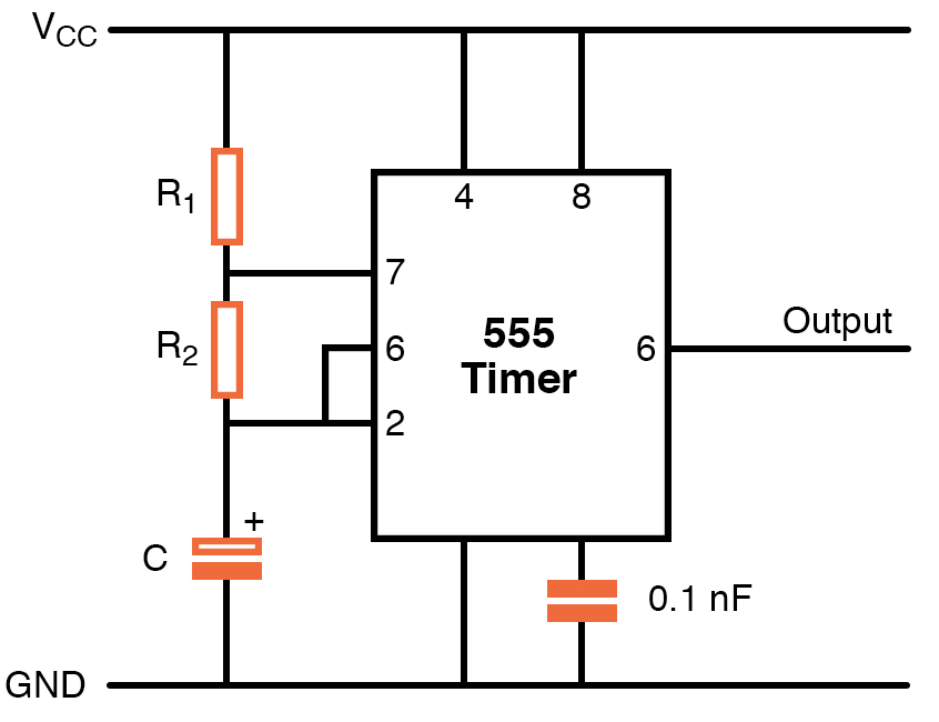
Knowing this, let's say HIGH time is 30 seconds and LOW time is five minutes. A 555 IC in astable mode is a very popular circuit where we need to select the values of resistors and timing capacitors to determine the length of time for the ON/OFF cycle. Here's a typical 555 IC circuit in astable mode:
A typical 555 IC circuit in astable mode.
Within this circuit:
- Timing capacitor C will increase the cycle time
- R1 will increase time HIGH
- R2 will increase time HIGH, increase time LOW and decrease the duty cycle
The component values are:
- C – 200uF
- R1 – 2 Mohm
- R2 – 220 Kohm
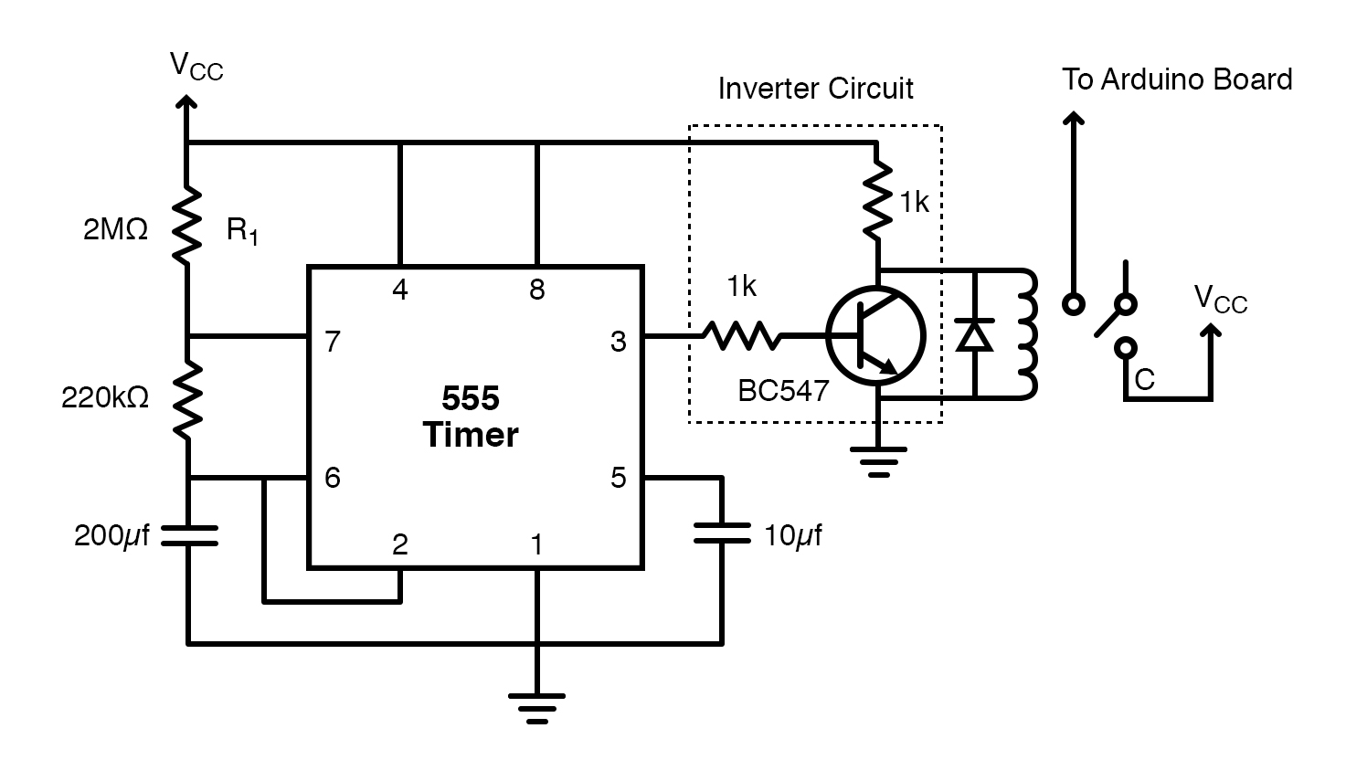
With this arrangement, we can achieve a duty cycle of 91%. After using a logic inverter, it would be around 9% according to our application’s needs.
Our NOT gate is made up of an NPN transistor. When a HIGH trigger pulse passes to the base of the transistor, it becomes active and the output is pulled low, else the output stays HIGH. We connect the output from the IC to a 5V relay and, upon switching the relay, power passes to the Arduino.
The circuit diagram for an external timer circuit.
Solar-powered Battery Charger Circuit
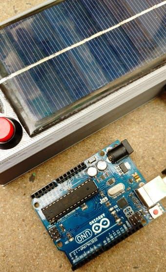
I made this circuit and added a solar panel as an external supply because finding a power outlet in remote locations where the weather stations or data loggers are generally used is a problem. Because of this, you will need a battery and a solar panel with a charging module and a boost converter module. The goal here is to make a solar-powered battery charger circuit first.
Adding a solar panel to this circuit powers projects in remote locations.
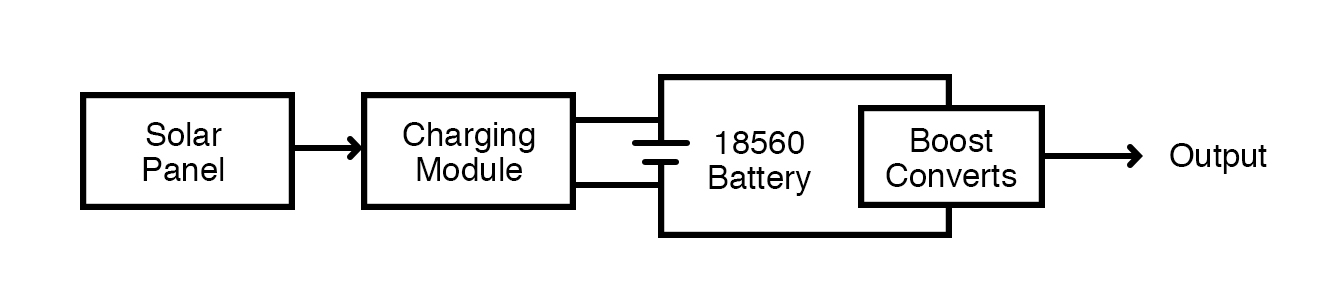
We will be using a TP4056 lithium battery charger module to change a 18560 lithium battery. The TP4056 module is a micro USB 5V 1A lithium battery charger module; it works with a linear charging method and offers adjustable charge current from 50mA to 1A with the help of an adjusting resistor. By default, the soldered resistor value is 1.2Kohm. It also has indicator LEDs to indicate charging completion.
To power our Arduino from the battery, we will need a boost converter module to achieve a stable 5V output.
How the solar panel powers the Arduino.
As we have made our powering station, let's compare power consumption with sleep mode and with the external circuit.
In Sleep Mode:
- Current consumption during ON time: 51.7 mA
- Current consumption during OFF time: 34.9 mA
With the External Circuit:
- Current consumption during ON time: 92 mA
- Current consumption during OFF time: 0.8 mA
You can see that during the majority of the time, the power consumption with the external circuit is negligible compared to sleep mode.
Sensor-based External Wake Up Circuit
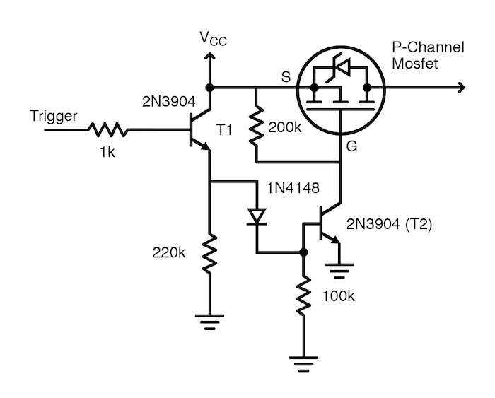
This circuit cuts off the power to the Arduino until it gets a high signal from the sensor. For example, when using this circuit in a project like a PIR motion detector, it will power Arduino when something is detected by the sensor and technically saying when the sensor sends a HIGH pulse.
The sensor-based external wake up circuit diagram.
The circuit is built around a P channel MOSFET and a couple of NPN transistors. When a HIGH pulse is applied to the circuit, transistor T1 becomes active and there is power reaching the base of transistor T2. So Gate pin of the MOSFET is pulled low and this allows the current to flow through the MOSFET and the board gets power.
We have seen here two external circuits that can reduce the power consumption of your Arduino projects and help increase the battery life.