This article shows you how you can program an STM32 F103C8T6 with Arduino IDE using UART.
The STM32F103C8T6 board — also called Blue Pill — is a development board for the ARM Cortex M3 microcontroller. It looks very similar to the Arduino Nano, but it contains a lot more features.
In this article, I will show you how to set up the STM32 with Arduino IDE and show you how to directly program from the USB UART module.
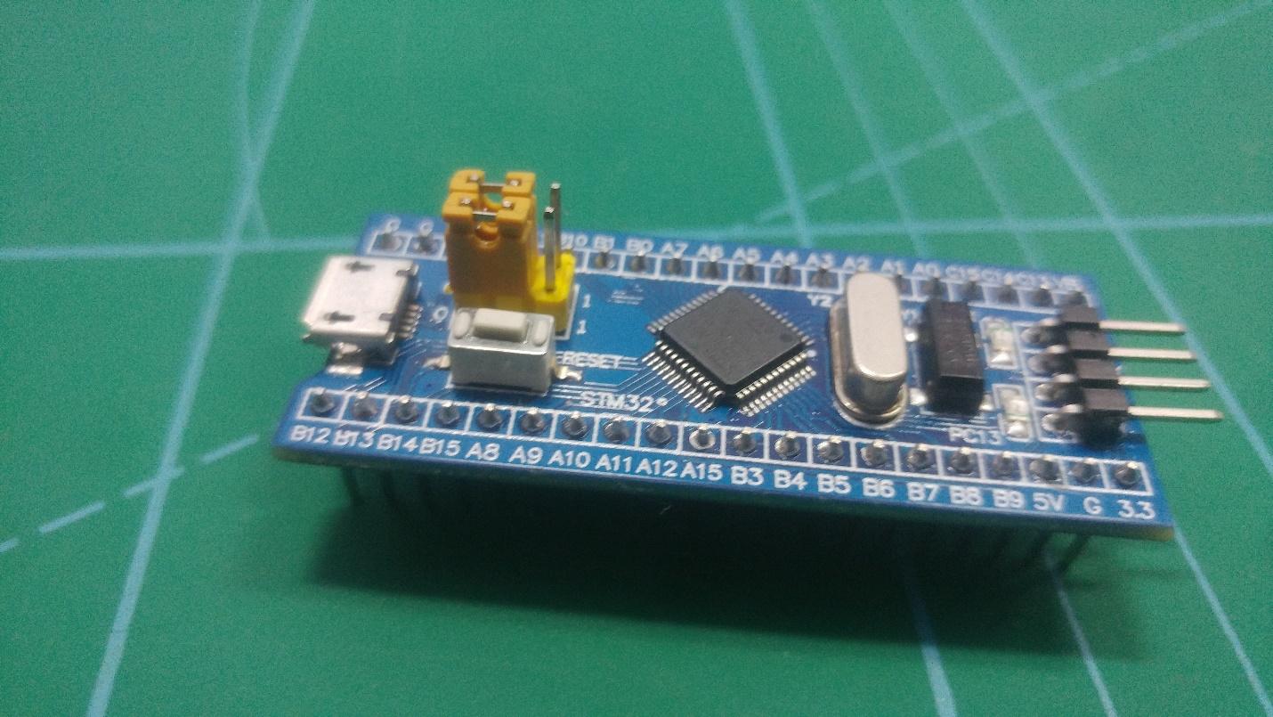
An Overview of the STM32 "Blue Pill"
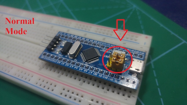
If you take a look at this $2 microcontroller, one of the first things you see are its jumper pins, which are used to work with the default USART boot loader. There is also a micro USB port on the board, but unfortunately it cannot be used for programming because it does not have an associated boot loader.
These boards are very cheap compared to the official Arduino board, and the hardware is open source. In addition to the microcontroller, the board can accommodate two crystal oscillators — one 8MHz crystal and one 32KHz crystal — that can be used to drive an internal RTC (real-time clock). As a result, the MCU can operate in deep sleep mode, making it ideal for battery-powered applications.
To program this board, we need to use a simple USB to UART converter, and then we can program it directly via USB from a computer.
Required Materials
- STM32 F103C8T6
- USB TO UART Converter (FTDI)
- Jumper wires
- Breadboard
- Arduino IDE
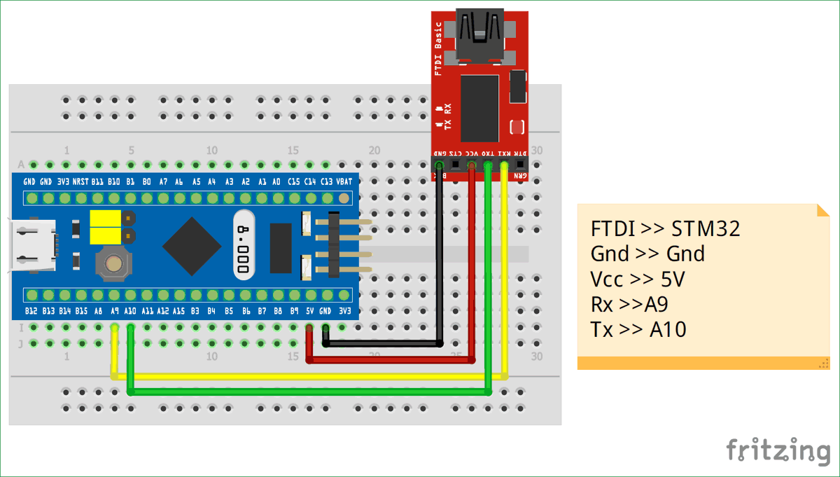
Wiring the Project
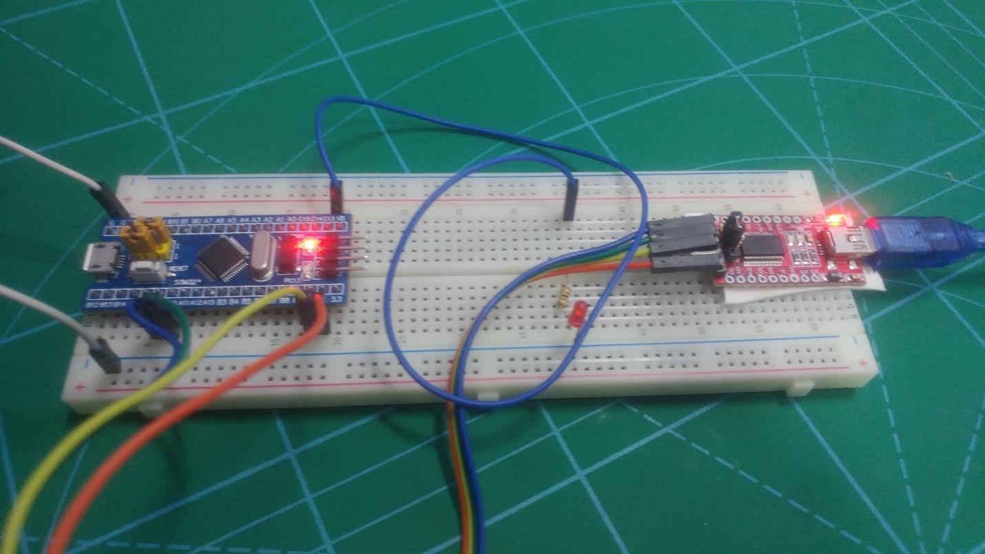
Connect the boards according to the connections shown in the Fritzing diagram below, and connect them with your computer.
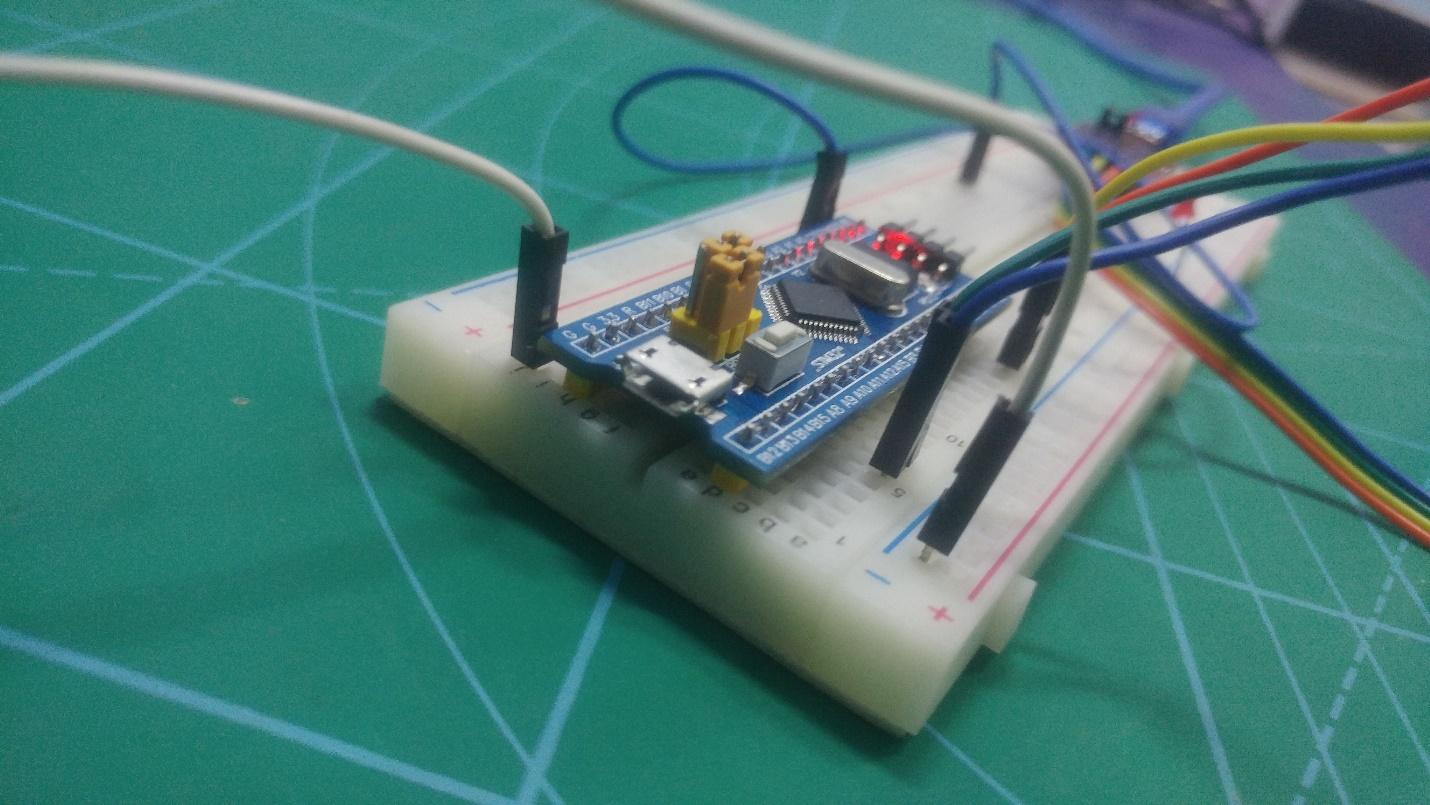
The build set up with the jumper wires in place.
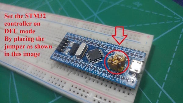
Connect the jumpers as shown below to set the board to DFU mode (device firmware upgrade) and press the Reset button.
Setting Up the STM32 on Arduino IDE
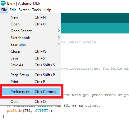
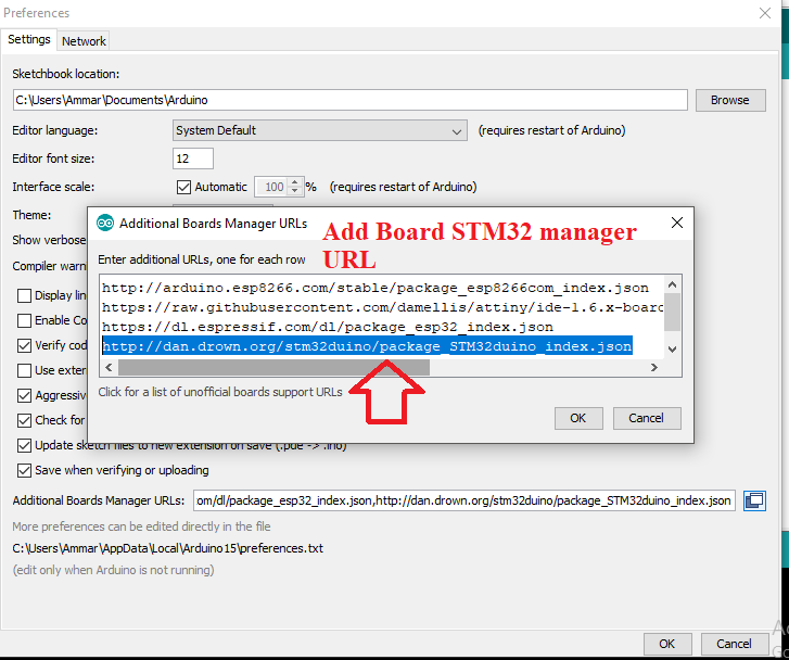
Open Arduino IDE and select Preferences.
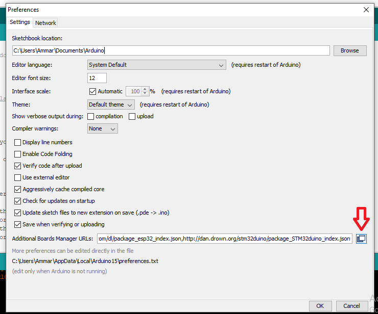
Click on the Additional Board URL option and add this URL after the comma:
http://dan.drown.org/stm32duino/package_STM32duino_index.json
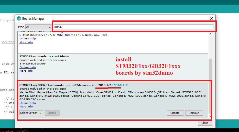
Next click on Tools → Board → Board Manager.
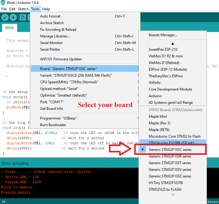
After performing the steps above, you can see the STM32 in the boards list. Now select the STM32F103C.
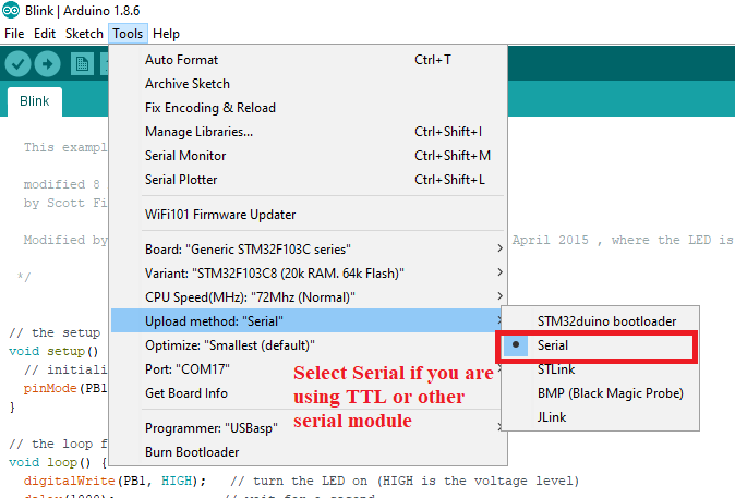
Because we are using a UART module for uploading the code, select Upload Method as Serial.
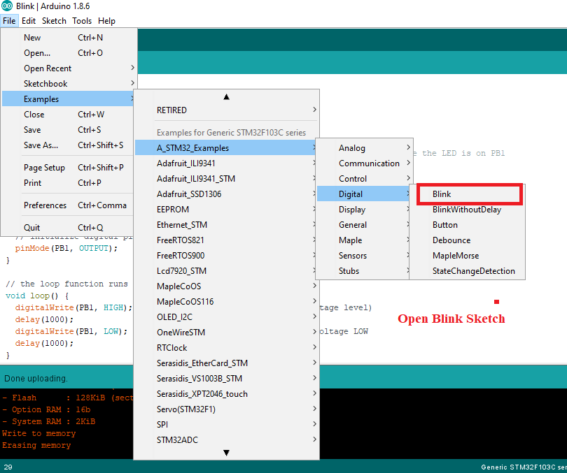
Choose the Blink sketch from the example.
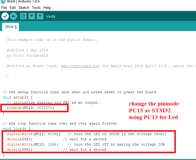
Change the LED pin number with “PC13” as shown in the screenshot below. This is the name of the built-in LED in the board.
Project Source Code
void setup() {
  // change pin PC13
  pinMode(PC13, OUTPUT);
}

//infinite loop
void loop() {
  digitalWrite(PC13, HIGH);   // turn the LED on (HIGH is the voltage level)
  delay(1000);              // wait for a second
  digitalWrite(PC13, LOW);    // turn the LED off by making the voltage LOW
  delay(1000);              // wait for a second
}
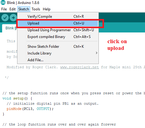
Upload Code to Arduino IDE
Conclusion
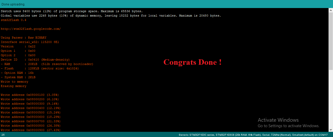
If the program has been successfully uploaded, you should see the green LED flash at 1-second intervals. You can also use this program to increase or decrease the delay of the LED light.
After uploading the program, you should change the jumpers back to Normal mode so that the next time when you start the board, the uploaded program will automatically start executing.