Learn how to stream live display using OV670 Camera Module onto a 1.8-inch TFT LCD screen using Arduino IDE.
In this article, I will show you how to display the stream from an OV7670 camera module onto a 1.8-inch TFT LCD screen using Arduino. OV7670 is the most affordable camera module that can be used with the Arduino, so you can use this in a lot of projects.
We will connect, configure, and get a test image from the OV7670 using a small program written in the Arduino IDE. This can then be the starting point for using it in future projects. We will be using indrekluuk library in this article and all the credit goes to the developer of this library. Let’s get started!
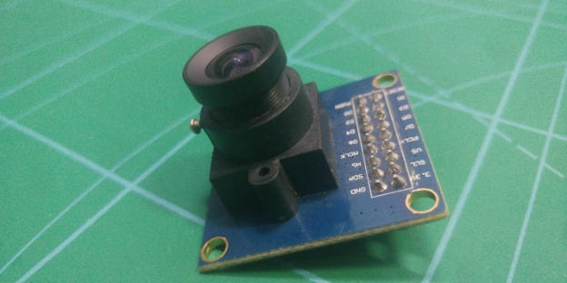
The OV7670 Camera Module
This module allows you to capture images in VGA format (640x480). It can perform some initial processing and transfer the images to microcontrollers, such as the Arduino, via the SCCB interface.
The camera unit allows you to form images in other formats like CIF (352x240) and others. Manual adjustments up to 40x30 are also possible. The maximum image transfer rate (VGA) can reach 30 frames per second. The camera also performs pre-processing of images, such as exposure control, amplification, white balance, and more.
Also supported are various image encoding options (YUV, various types of RGB). Data transfer is carried out using the SCCB protocol.
OV7670 Specs
- VGA resolution (640 x 480)
- QVGA (320 x 240)
- CIF (352 x 240)
- QCIF (176 × 144);
- Transmission speed up to 30 fps,
- several ways to encode the image RAW RGB, RGB 565/555, YUV / YCbCr 4: 2: 2
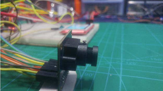
The OV7670 camera module.
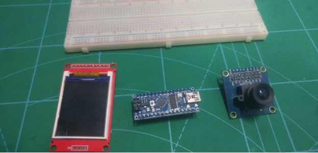
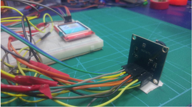
From left to right: the TFT display, Arduino nano, and OV7670.
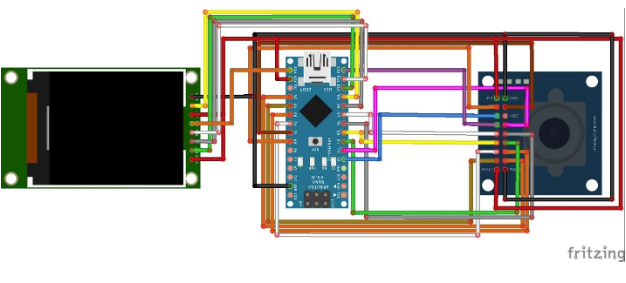
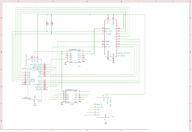
Wiring the Project
Let's start by assembling all components as shown in the diagram below.
Connections Between the OV7670 and Arduino Nano
OV7670 | Arduino Nano |
|---|
VSYNC | PIN2 |
XCLCK | PIN3(must be level shifted from 5V => 3.3V) |
PCLCK | PIN12 |
SIOD | A4 (I2C data) |
SIOC | A5 (I2C clock) |
DO D3 | A0.. A3 (pixel data bits 0..3) |
D4 D7 | PIN4..PIN7 (pixel data bits 4..7) |
3.3V | 3.3V |
RESET | 3.3V |
GND | GND |
PWDN | GND |
Connections Between the TFT Display and Arduino Nano
DC | PIN 8 (5V => 3.3V) |
|---|
CS | PIN 9 (5V => 3.3V) |
RESET | PIN 10 (5V => 3.3V) |
SPI data | PIN 11 (5V => 3.3V) |
SPI clock | PIN 13 (5V => 3.3V) |
VCC | 5V/3.3V (depending on jumper position on the TFT board) |
BL | 3.3V |
GND | GND |
Compiling in Arduino IDE
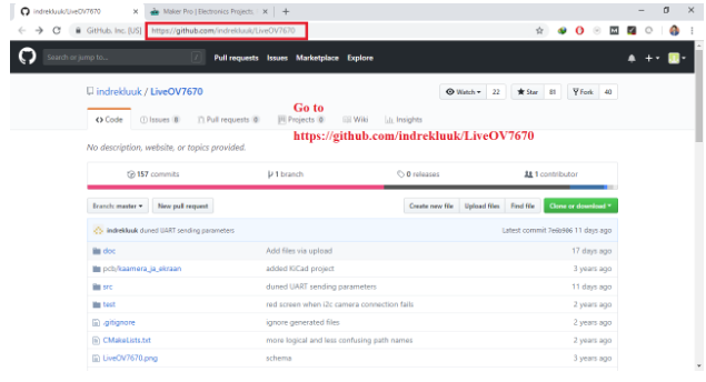
Download all files
- copy "src/lib/LiveOV7670Library" and "src/lib/Adafruit_GFX_Library" to Arduino "libraries" folder (If you already have "Adafruit_GFX_Library" then you don't have to copy that)
- Open "src/LiveOV7670/LiveOV7670.ino" in Arduino IDE
- Select Tools->Board->Arduino Uno/Nano
Setting Up the Program Step by Step
You can also complete the actions step by step with the following screenshots.
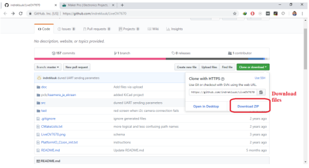
Click on "download ZIP", to download the complete files.
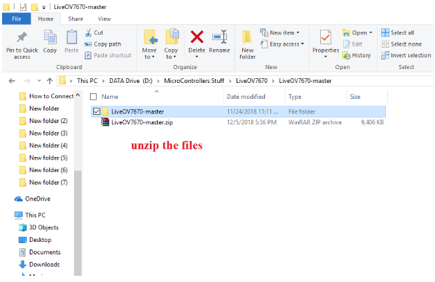
Once downloaded, unzip the files to your desired folder.
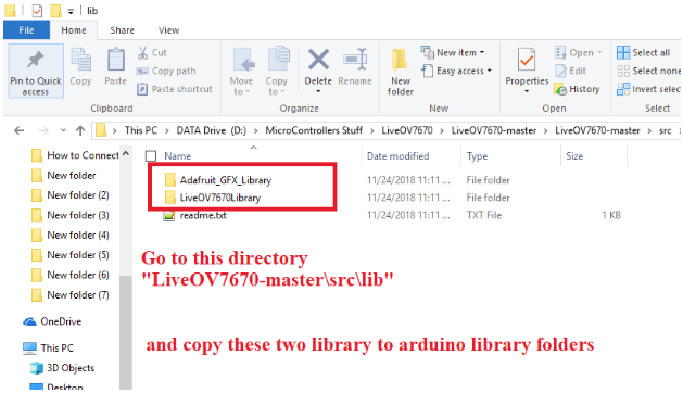
Open the unzipped folder and go the this directory: "LiveOV7670-master\src\lib". Copy the two folders to your Arduino Library folder.
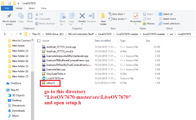
Go to "LiveOV7670-master\src\LiveOV7670". Open the file named setup.h.
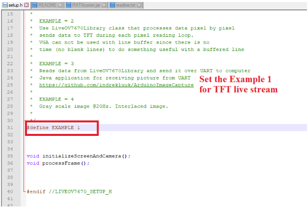
Changing the value of Example 1 to Example 3 as shown in the screenshot below will have the camera broadcast the image directly to the computer.
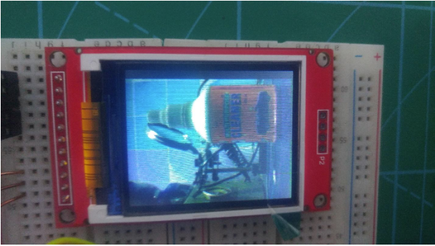
When Example 1 is set, the camera transfers the image directly to the LCD which is connected via the SPI interface using “LiveOV7670Library” Library.
Set Example 1 for TFT live stream.
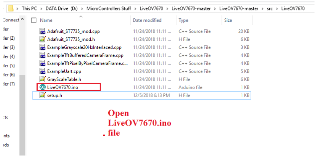
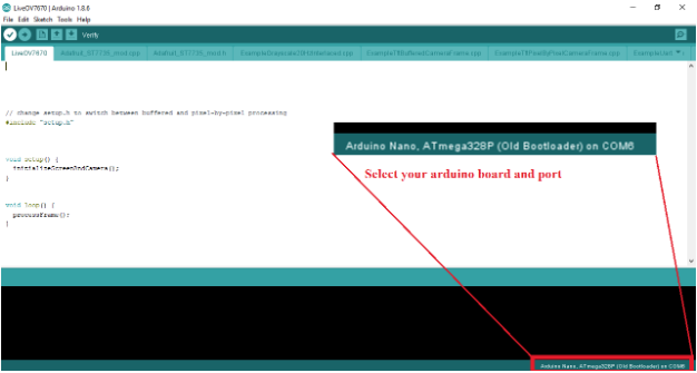
Next, open the file LiveOV7670.ino.
On the lower right portion of the screen, select your Arduino board and Port.
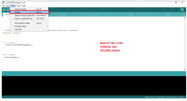
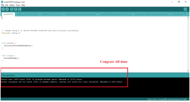
Upload the code from above without any modifications.
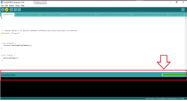
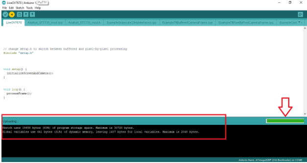
You will see a notification that the program is compiling as shown above.
Conclusion
This cheap and easy-to-use Arduino-compatible camera is useful for video surveillance projects or as a vision system for robotics using platforms like OpenCV. It is also possible to use as a normal webcam.