Having the right tools for your project is essential, learn how to prototype easily with this multi function shield!
Simple I/O often takes up most of our attention while working on a project. Tasks such as reading keys, putting text to a display, and triggering an alarm often hamper the focus of the main task when developing with a microcontroller.
It is for this reason that a multi-function shield and library have been developed for use with Arduino to allow us to use the preferred input or output hardware of our choice while simplifying basic I/O operations. Moreover, the examples provided in the Arduino multi-function shield library simulate many real-world applications that can just be deployed, so that Arduino beginners can easily experiment and build upon them.
In this tutorial, I’ll show you how to interface a multi-function shield with an Arduino and get prototyping!
The Multi-function Shield for Arduino
The multi-function shield I used in this particular tutorial is from AliExpress, but there are many other vendors who provide the same Arduino shield.
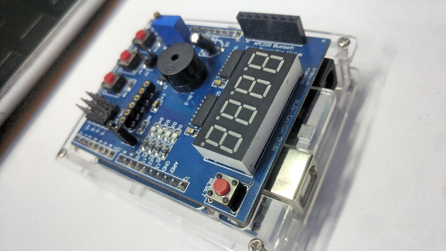
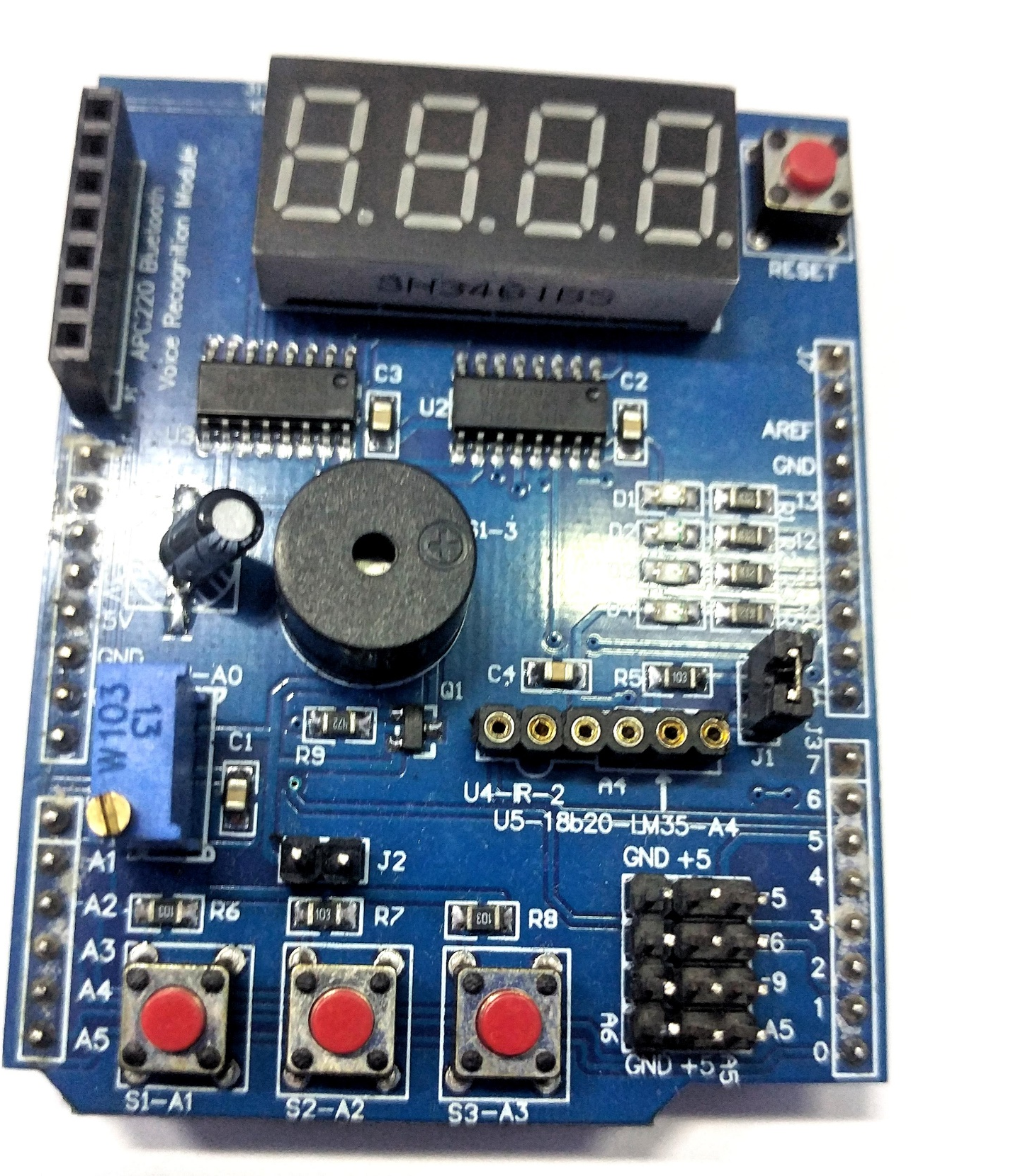
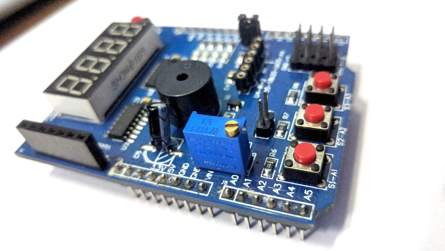
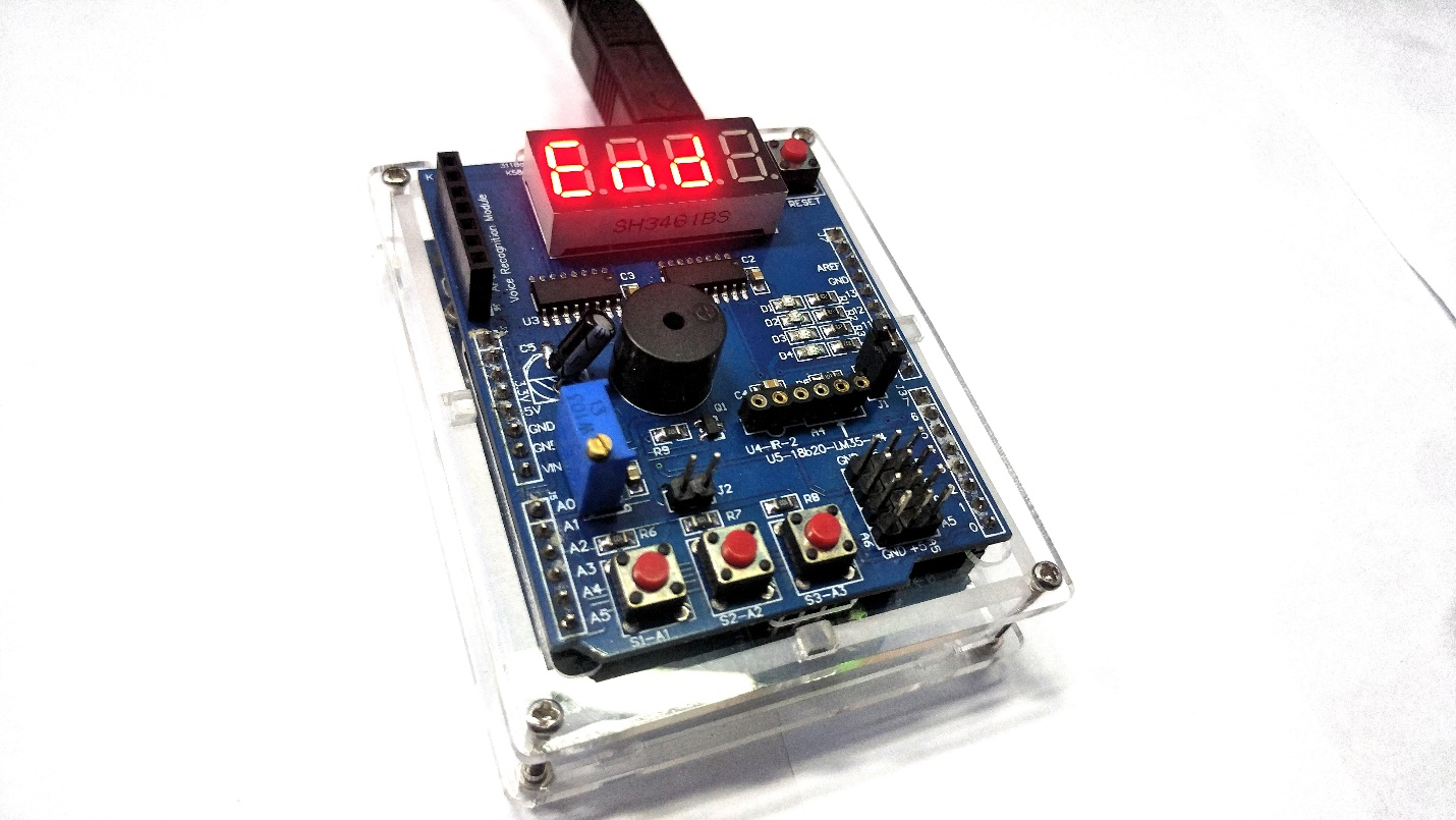
The multi-function shield
Arduino Shield | DATASHEET PIN # |
|---|
Buzzer | Pin 3 |
4-digit 7-segment LED tube driven by 74HC595 | Latch 4, Clock 7, Data 8 |
A Reset Button and three programmable buttons | A1, A2, A3 |
Header for APC220 shield | GND, +5v, 0, 1 (rx/tx) |
Potentiometer (10 kOhm) | A0 |
Female header for temperature sensor LM35 or DS18B20 | A4 |
Socket for infrared receiver | 2 |
Free pins (pwm) | 5 6 9 A5
|
4LED lights on the shield | 10, 11, 12, 13
|
You can also find a connector with 4 free pins, 4-pin GND, and 4 + 5V pins. I dug around the internet and found its datasheet and some sample C programs.
Required Hardware
Required Software
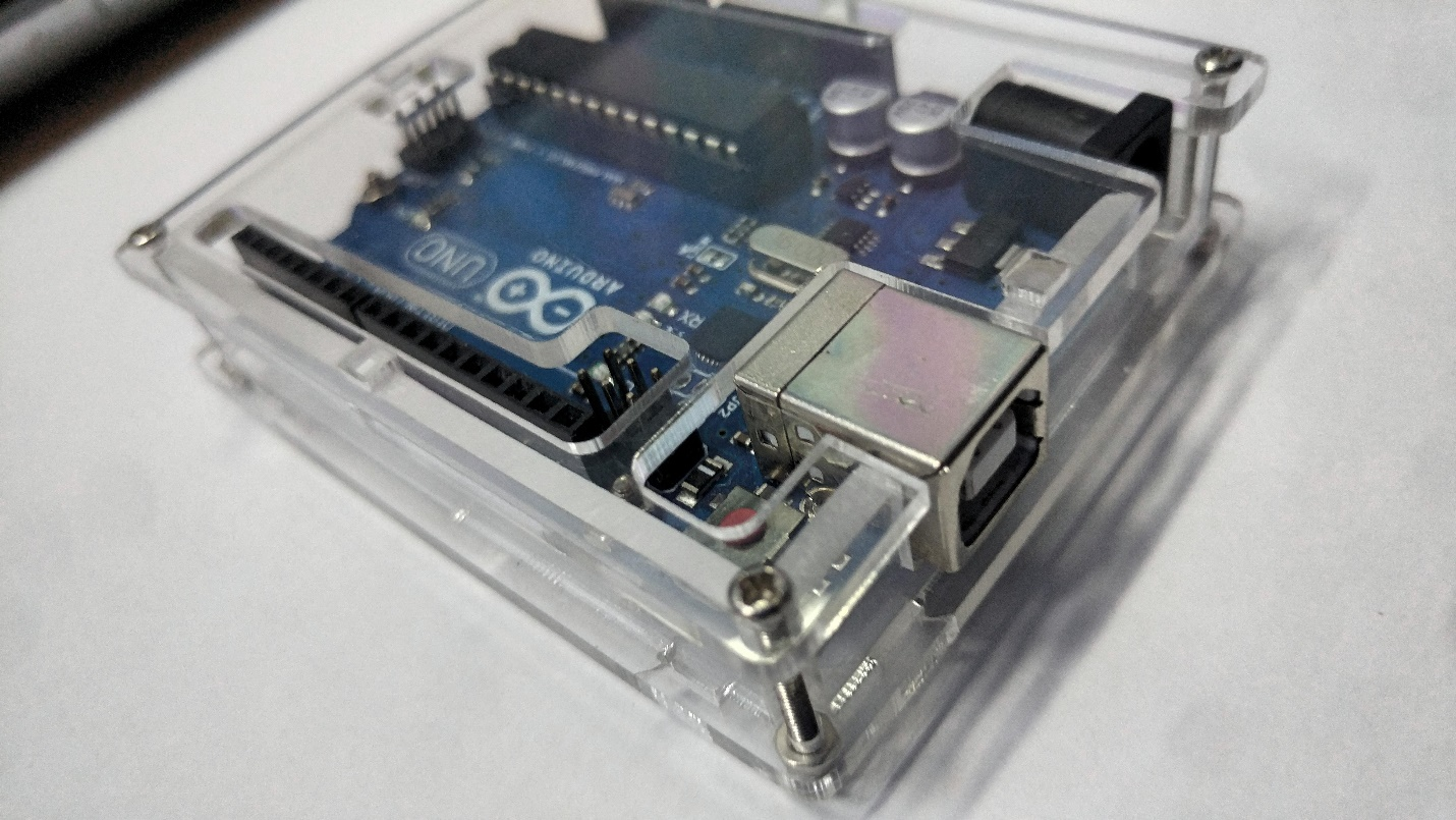
Arduino UNO (case optional)
Multi-function shield for Arduino
Testing the Arduino Multi-function Shield Display
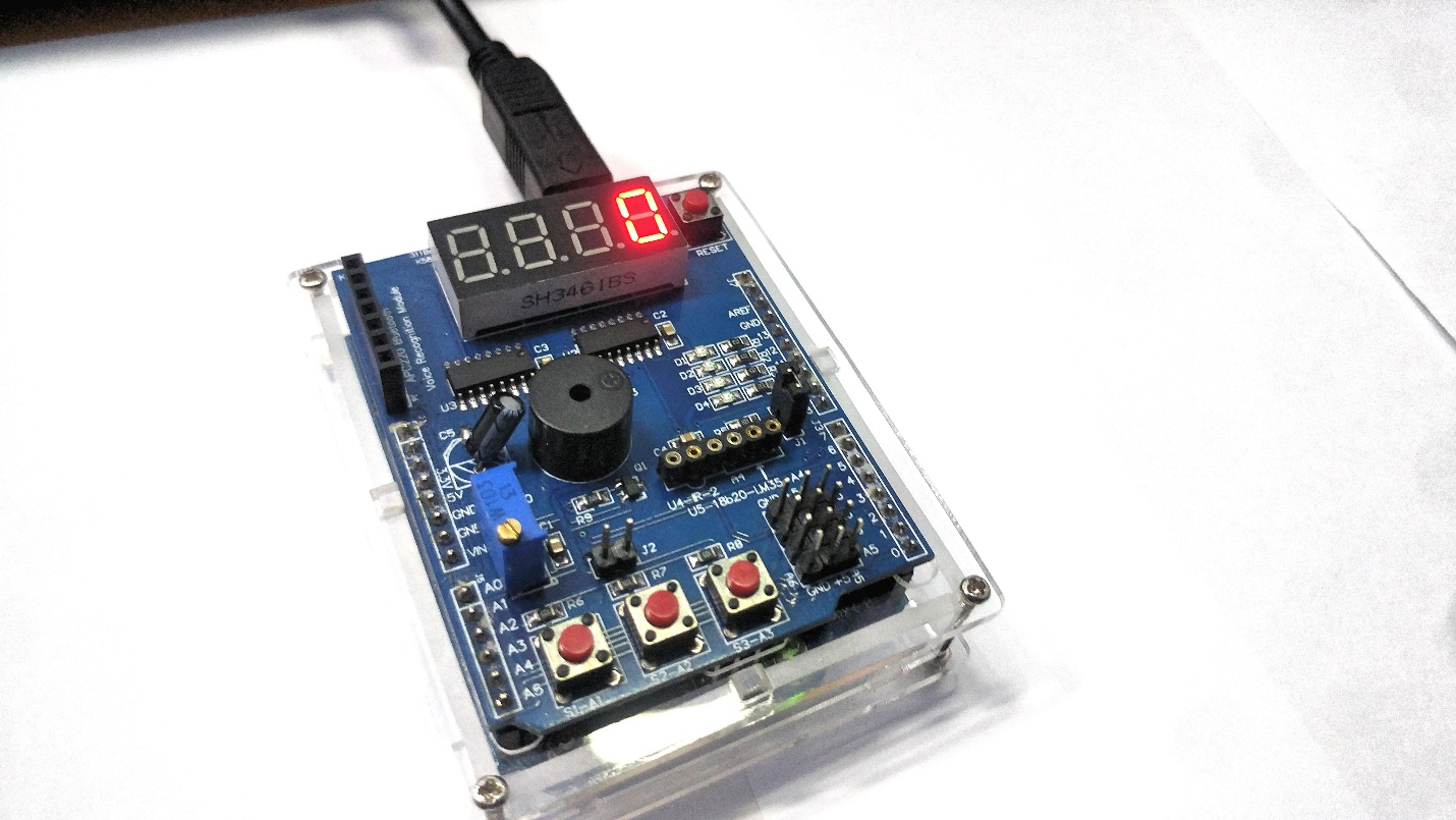
Since the management of the versatile shield digital display is performed in the background using interrupts, our application can continue to focus on performing its main tasks. Strings, integers, and floating-point values are written to the display as shown in the following image.
Testing the Real-time Application Counter Timer
The real-time application counter timer is very similar to the counter timer you might find in a microwave oven. Button 1 on the shield starts the time, button 2 sets the minutes, and button 3 sets the seconds.
The real-time application counter timer
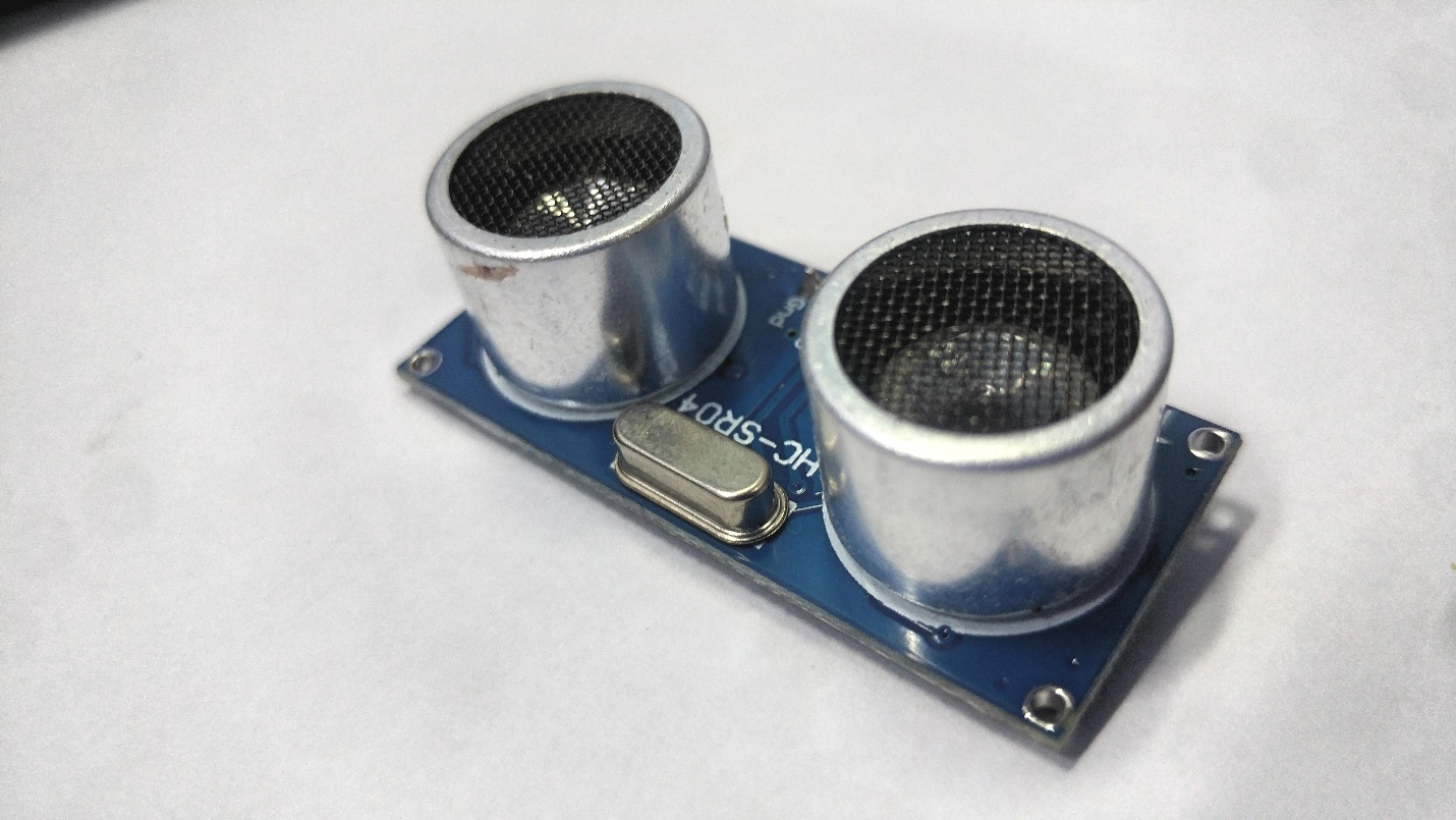
Using the HC-SR04 With the Multi-function Shield
We’ll also experiment with this Arduino shield and see how we can interface it with external sensors (in particular, the HC-SR04) to allow us to read temperature values, calculate distance, and detect motion.
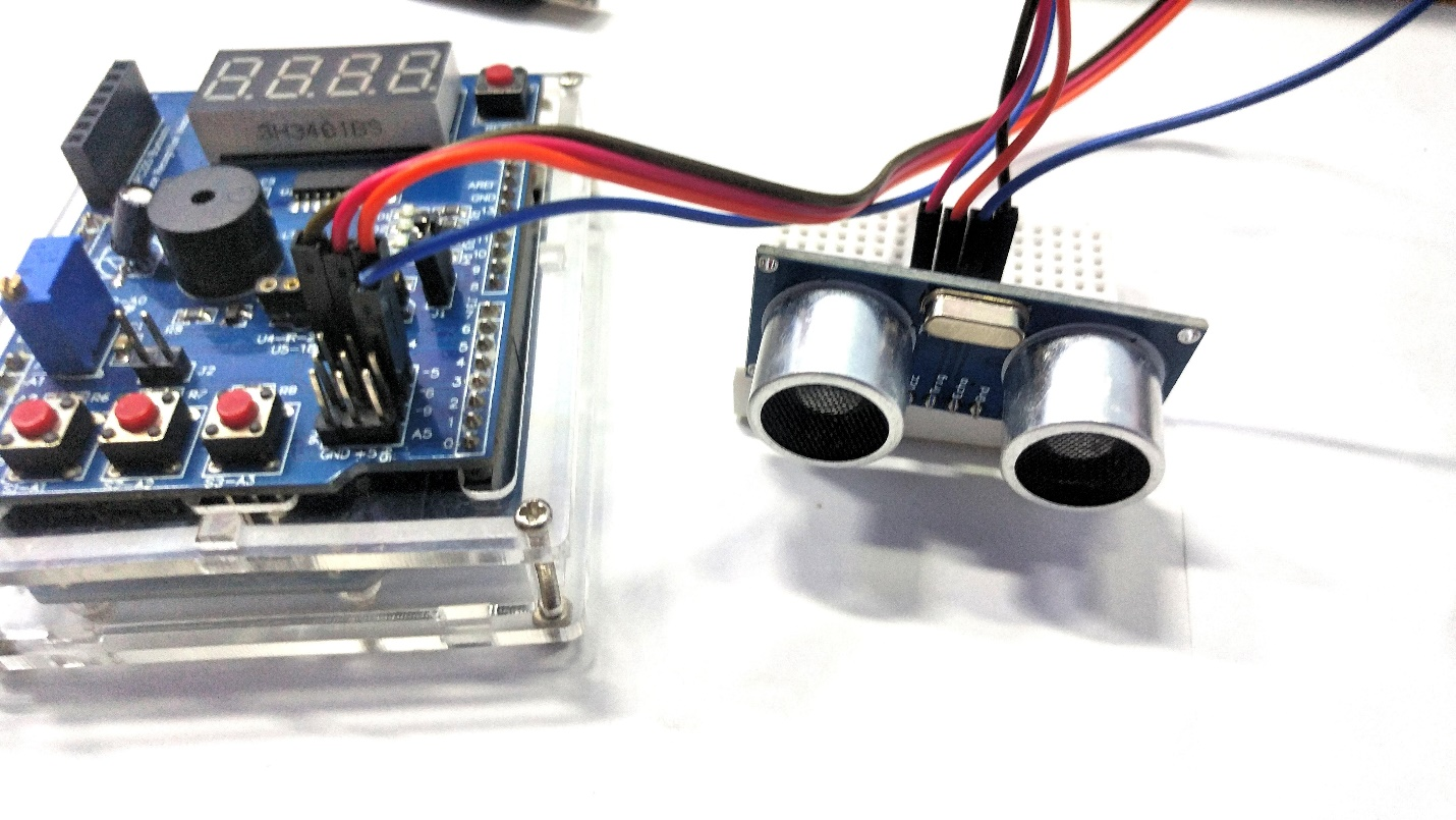
If the interrupt is turned on when using the HC-SR04 ultrasonic proximity sensor, it is recommended to use the multi-function mask library to read and calculate the distance value. This is preferable because the interrupt service routine of the library will mess with the timings of the HC-SR04. Therefore, it needs to be compensated.
Moreover, with the additional three levels of filtering provided by the library, smoothing out the readings from the HC-SR04.
Using the multi-function shield with an HC-SR04
I hope this tutorial has helped you get familiar with this multi-function shield. Use the shield for projects that require quick prototyping to save yourself a lot of time from setting up displays or other peripherals.