Learn how you can control stepper motors with an Arduino UNO to enable more accurate movement in robotics.
This tutorial will teach you how to control stepper motors to get fine rotation and perfect angular control — a key skill for robotics projects.
Why Use Stepper Motors?
Stepper motors are brushless DC motors with many internal teeth that magnetically lock into position with surrounding copper coils. Unlike brushless motors, applying power to a stepper motor will not make it turn. Instead, it locks into a position specified by the inputs given and turns either clockwise or counterclockwise by a small step.
While this makes driving stepper motors more complex, there is a major advantage over brushless DC motors: their angular position can be specified with a great degree of accuracy. For example, if you want a motor to rotate exactly 270 degrees, this would be near impossible to do with a general DC brushless motor (without some form of feedback) but would be a breeze with a stepper motor.
A stepper motor requires a number of step pulses to get to your desired position. Also, stepper motor coils are always energized, greatly increasing the holding torque, but turning it forcibly is difficult. These advantages explain why stepper motors are commonly used in many applications including CNC machines and CD/DVD drives.
Stepper motors come in two phases: unipolar and bipolar. Unipolar motors contain a common source connecting all the coils, whereas bipolar motors have separated coils.
This article only looks into unipolar motors, because bipolar motors need to be driven differently.
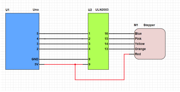
Schematic
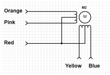
Unipolar Input and Stepping
Unipolar motors typically have 5 input wires—two paired wires to control a coil and a fifth wire to provide the common tap for each coil.
While the wire colors differ from motor to motor, here are the connections used in this article:
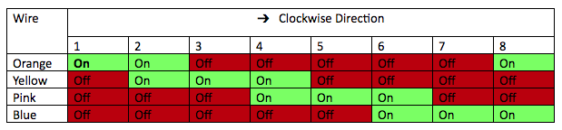
The table below shows how to drive each input to rotate the motor. Moving forward (i.e., from step 1 to 2) makes the motor turn clockwise while moving backward makes the motor turn counter-clockwise.
Table 1. Motor Rotation Status
Stepper motors may require current far exceeding the limits of microcontrollers, which is why a microcontroller must NEVER be directly connected to a motor. Motors can also induce back EMF, potentially damaging I/O ports and making the use of clamping diodes an absolute must.
However, driving a stepper motor with four discrete transistors would be wasteful and bulky, which is why the ULN2003 stepper driver IC is necessary. This IC contains seven Darlington transistors that each include diode protection and are capable of providing a 500mA, 50V output (which is actually more than the Arduino Uno can handle).
Coding the Stepper Motor
Coding the stepper motor steps can be done with a switch statement and some I/O bits but there is an easier way: use the built-in Stepper Library!
While the Arduino is a convenient and simple platform, its library support is what makes it one of the best platforms—most modules on the market are compatible via Arduino libraries. In the case of stepper motors, we can easily control them with the stepper library and there is no need to code each step.
#include <Stepper.h>

#define STEPS_PER_REV 513

// Create our stepper motor object
Stepper motor(STEPS_PER_REV, 2, 3, 4, 5);

void setup() {
  motor.setSpeed(10);               // Motor speed of 10 RPM
}

void loop()
{
  motor.step(STEPS_PER_REV);        // Step clockwise one whole revolution
  motor.step(STEPS_PER_REV / 2);    // Step clockwise half revolution
  motor.step(-STEPS_PER_REV);       // Step counter clockwise one whole revolution
}
To use the stepper motor library we first need to include the stepper library header:
The next step (which is optional but recommended), is to define the number of steps you want the motor to rotate in one complete revolution. The motor used in this tutorial has 32 steps and is connected to a reduction gear with a ratio of 1:16, so the number of steps for one revolution is 513.
#define STEPS_PER_REV 513
Now that we have the number of steps defined, we need to create a stepper motor object. This object is initialized with five variables: the number of steps per revolution and the four pins that connect to the stepper motor.
Stepper motor(STEPS_PER_REV, 2, 3, 4, 5);
In the setup function, we can define the speed (in RPM) we want our motor to turn.For this example, we have set the RPM to 10.
void setup() {
  motor.setSpeed(10);               // Motor speed of 10 RPM
}
The main loop holds the code needed to turn the motor. Positive numbers step the motor equal to that number of times forward, while a negative number rotates the motor in the opposite direction.
The three lines of code in this example show how the STEPS_PER_RPM can be used to turn the motor by a known amount.
motor.step(STEPS_PER_REV);        // Step clockwise one whole revolution
motor.step(STEPS_PER_REV / 2);    // Step clockwise half revolution
motor.step(-STEPS_PER_REV);       // Step counter clockwise one whole revolution