In this part of this series on Robotic Arms control, learn to build a very simple robot arm with the Arduino and ROS.
Robot Operating System (ROS) is the leading robot control middleware/software. The complete ROS ecosystem provides all the tools needed to implement algorithms for robot kinematics, dynamics, motion control, motion planning, perception, and simulation. In the previous article How to Use Arduino With Robot Operating System (ROS), we learned how to use ROS with Arduino and used ROS to simulate random motion sequences on a virtual robot arm.
This article takes another step towards building a very simple robot arm with the Arduino and using ROS for real-time robot control and motion.
This article takes another step towards building a very simple robot arm with the Arduino and using ROS for real-time robot control and motion.
Designing the Robotic Arm
I built a simple 5-DOF robot arm. The robot only has revolute joints powered by SG90 low torque and inexpensive hobby servo motors. These motors are position-controlled and need PWM signals for movement. For low-level control of the servos, an Arduino Uno is used.
You can find the code on my GitHub. The hardware components used here are:
- SG90 Servo Motors (5)
- Arduino Uno R3 Development Board
- Cardboard to fabricate robot arm links
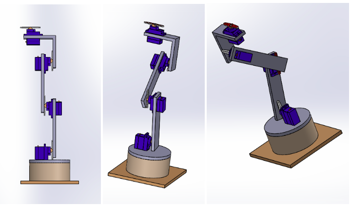
I built a 3D CAD model of the robot for measurements and 3D printing. I made the robot out of cardboard but readers are encouraged to use the CAD models and 3D print the parts. The CAD files can be found in the Github repository.
Robot 3D Model. First image is the robot home position (Image Source - Original)
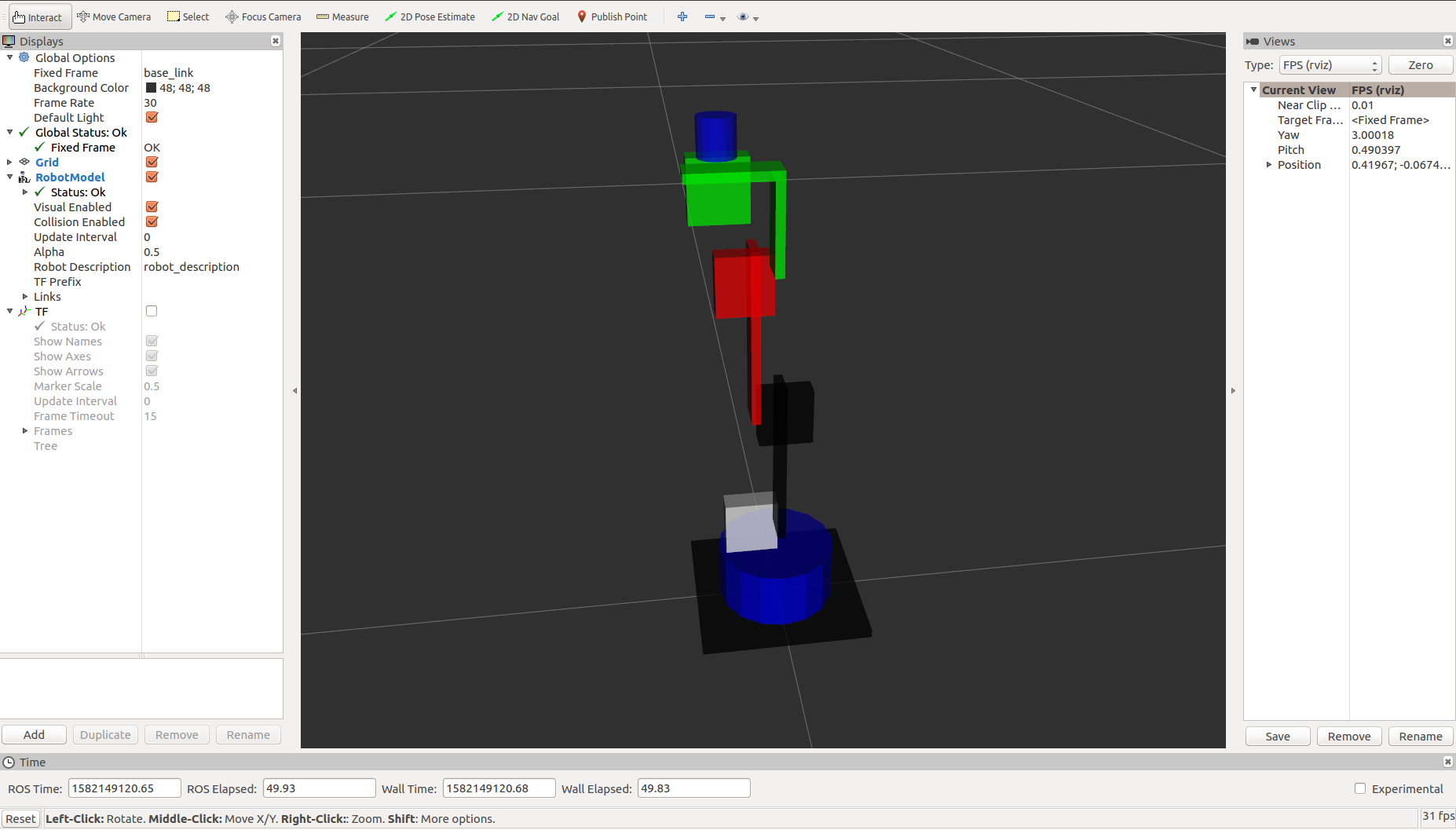
The robot arm URDF in the previous article on Robotic Arm Simulation in Robot Operating System (ROS) was a very rudimentary design. For this project, I created a URDF using coarse approximations for the servos and the joints. Readers can try creating the URDF using STL files provided in the repository. The virtual model of the robot has the same visual and collision links. The robot joints are named joint_0, joint_1, joint_2, joint_3, and joint_4 with joint_0 at the robot base.
Note: The first servo for joint_0 sits inside the circular disc platform. It is not visible in the URDF but can be seen in the exploded view of the CAD model.
Robot URDF model.The servos are represented as consolidated blobs and the blue end-effector is for visualization purpose only. - (Image Source - Original)
Building the Robot Hardware
For the ease of fabrication, I used easily available cardboard. There were only a few parts that I cut out and put together using super glue. You can refer to the CAD files for measurements.
The SG90 servo motors used here have an angular range of 0-200°. The joint angle limits in the URDF file are mentioned as ±90° centered at home. The homing offset is done in the Arduino code.
Note: When mounting the links to the servos, make sure you drive the servos to the home position at 90° such that the links have a ±90° motion in either direction of rotation.
Interfacing the Robot Arm With Arduino
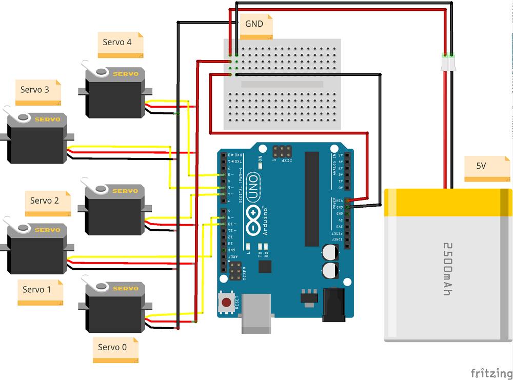
Servo motors need PWM signals for motion and several digital pins on the Arduino Uno are capable of generating PWM signals. These digital pins are used to connect the servos. The connections are shown in the diagram below.
Servo motor connections with Arduino (Image Source - Original on Fritzing)
Setting Up the Infrastructure
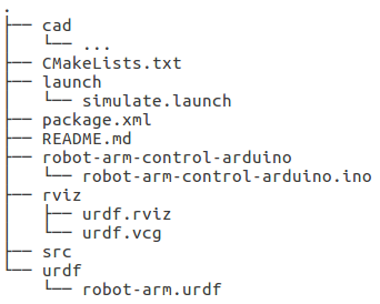
File Structure for the ROS package- (Image Source- Original)
- cad - All the STL files for the 3D robot model.
- CMakeLists.txt - Script for CMake meta build system
- robot-arm-control-arduino - Arduino code that talks to the ROS nodes
- launch - Contains launch files for the Rviz simulator
- src - Contains the node that publishes the joint instructions to Arduino
- urdf - Contains the URDF model of the robot
- rviz - Contains the default configurations for the Rvix simulator
Code and Explanation
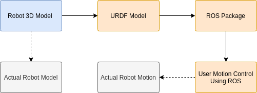
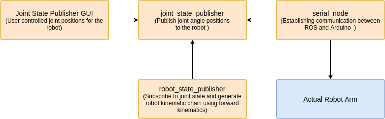
ROS instruction pipeline (Image Source - Original)
Launch file
The launch file is similar to the one used in the previous article. It launches the robot_state_publisher node and visualizes the URDF model on Rviz. It also launches the joint_state_publisher node which creates a GUI with sliders to control each joint of the servo. These joint instructions are published to the joint_states topic used by the robot_state_publisher as well as the Arduino (to know the use desired joint angles for the robot) via the serial_node that facilitates the communication to control the real robot.
Arduino Code
The Arduino Code is self-explanatory and well commented, but here are a few suggestions for readers who want to extend the code:
- Inside the loop() function, the call to node_handle.spinOnce() is made to ensure that ROS processes all the messages, subscriber callbacks, and other buffers. Readers can use node_hanlde.spin() for an infinite loop outside the Arduino loop() method.
- In the setup() method, it is important to set the baud rate prior to calling init() on the node_handle() else the baud rate is not correctly set and causes communication issues.
- The call made to writeServos() to update the servo positions directly sets the servo positions to use desired values resulting in a jerky motion. Readers can implement interpolated or profiled motion for smoother motion.
- The Arduino Uno used here has low buffer and memory which causes performance issues when multiple memory consuming messages are used. Switch to an Arduino Mega to avoid such situations.
Program Execution
Connect the Arduino Uno to the laptop via the USB cable and confirm that the board appears in the list of available serial ports in the Arduino IDE. Compile the code, select the board type, and upload it to the board.
Once the code is uploaded, execute the following commands in multiple terminals on the machine simultaneously.
- Start the ROS Master - roscore
- Run rosserial client on the machine - rosrun rosserial_python serial_node.py _port:=/dev/tty<USB# or ACM#> _baud:=115200
- The serial port is determined at run time for either ttyUSB or ttyACM. The exact port number can be found
- from the Arduino IDE or using dmesg | grep tty.
- Run the launch file to simulate and control the robot. - roslaunch robot-arm-control-ros simulate.launch
- The Arduino can now see the joint_states topic and the data being published to it by the GUI thereby controlling the servos on the robot.
Conclusion
Interfacing Arduino and ROS for real-world applications is very interesting and opens up the opportunity to explore rigorous software development in ROS. Until this article, we controlled the robot in the joint state for teleoperation but the real essence of robot arm control lies in using kinematics and dynamics of the system.