Learn how to interface the STM32 Blue Pill with a 16x2 character LCD module using Arduino IDE.
The STM32F103C8T6 module, also known as the Blue Pill module, is a very pocket-friendly alternative to the Arduino. In projects where you want to use a lot of cheap boards, these boards come in handy.
I previously covered the basics of getting started with the Blue Pill module, which showed you how to integrate the board into Arduino IDE. Check out that article before proceeding to this tutorial.
In this tutorial, I will show you to set up the Blue Pill with a 16x2 character LCD, which can be used in a variety of your projects.
What are LCDs?
LCDs are probably the most popular visual feedback devices used in projects. Whether you’re building an MP3 player project and want to show the name of the track being played or creating a quadcopter console that displays flight telemetry, this tutorial will come in handy for working with the Blue Pill.
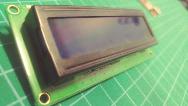
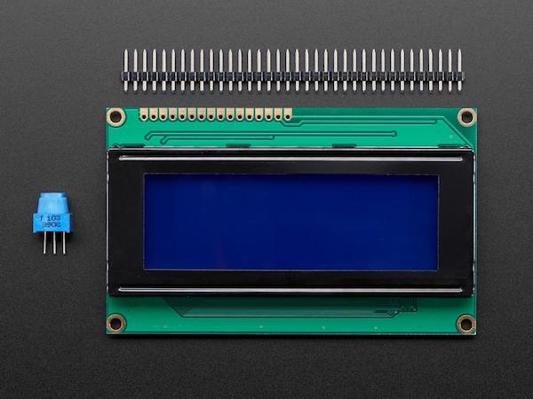
The LCD module used in this tutorial.
In addition to 16x2, you can find 20x4 character displays (four lines of 20 characters each). Green-black and blue-white are the most popular colors for these displays. There are also other variants that have a graphic display with a resolution of 128x64 pixels.
An example of a 128x64 pixel LCD graphic display.
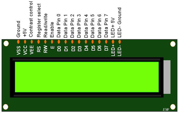
16x2 Character LCD Pinout
This character 16X2 LCD has 16 pins, shown in the diagram and table below.
Pin | Name | Function | Description |
|---|
1 | Vss | Power | GND |
2 | Vdd | Power | + 5V |
3 | Vee | Contrast Adj. | (-2) 0-5V |
4 | RS | Command | Register Select |
5 | R/W | Command | Read/Write |
6 | E | Command | Enable (strobe) |
7 | D0 | I/O | Data LSB |
8 | D1 | I/O | Data |
9 | D2 | I/O | Data |
10 | D3 | I/O | Data |
11 | D4 | I/O | Data |
12 | D5 | I/O | Data |
13 | D6 | I/O | Data |
14 | D7 | I/O | Data MSB |
Hardware Requirements
- 16×2 LCD display
- FTDI Programmer
- STM32 Blue Pill Development Board
- Jumper wires
- Breadboard
Hardware Connections
Wire up the hardware as shown in the diagram below.
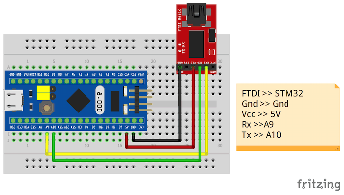
Connecting the STM32 to the FTDI programmer.
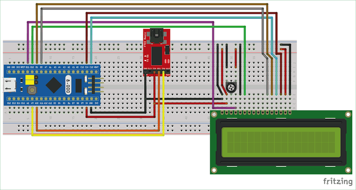
Connecting the LCD module to the STM32.
Use the connections table below to help guide you along with the Fritzing diagrams above.
LCD Pin Number | LCD Pin Name | STM32 Pin Name |
|---|
1 | GND | Ground (G) |
2 | Vcc | 5V |
3 | Vee | Ground (G) |
4 | Register Select (RS) | PB11 |
5 | Read/Write (R/W) | Ground (G) |
6 | Enable (EN) | PB10 |
7 | DB0 | No Connection |
8 | DB1 | No Connection |
9 | DB2 | No Connection |
10 | DB3 | No Connection |
11 | DB4 | PB0 |
12 | DB5 | PB1 |
13 | DB6 | PC13 |
14 | DB7 | PC14 |
15 | LED Positive | 5V |
16 | LED Negative | Ground (G) |
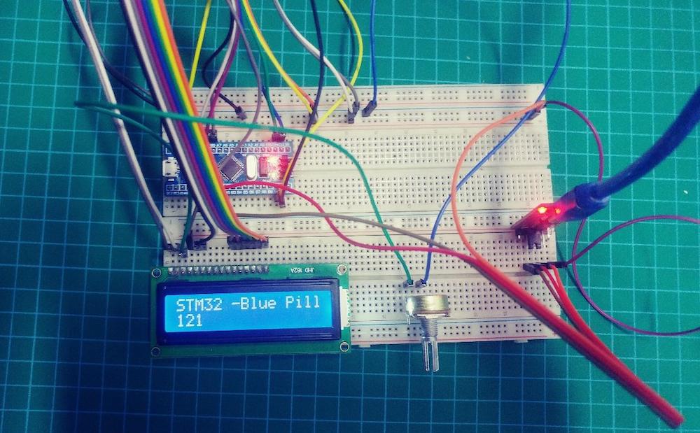
The hardware all connected.
Uploading the Code Into Arduino IDE
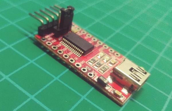
You will need a USB to UART converter for connecting this board to the Arduino. Again, the steps for hooking that up can be found in detail in Getting Started With the Blue Pill.
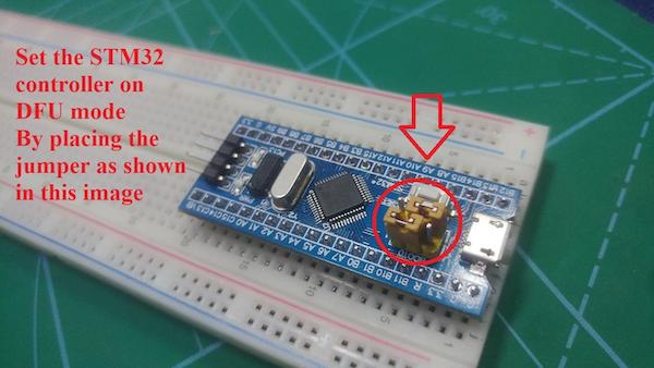
Copy the code found in a Zip file at the end of the article into Arduino IDE and, before uploading the program, make sure that the boot 0 jumper is set to 1 as shown in the image below. Then press the reset button.