Learn what a moving average filter is and how you can use it to remove noise from your next project!
Sensors and microcontrollers allow us to turn real-life phenomena into simple numerical signals that we can learn from. However, the raw output from the sensor may not be sufficient to extract desired information from. Real hardware is susceptible to noise and other interference from the environment.
The moving average filter is a simple technique that makers can use to smooth out their signal, removing noise and making it easier to learn from the sensor output. This article introduces the concept of a moving average filter and how to incorporate it into a design.
What is a Moving Average Filter?
A moving average filter is a basic technique that can be used to remove noise (random interference) from a signal. It is a simplified form of a low-pass filter.
Running a signal through this filter will remove higher frequency information from the output. While a traditional low pass filter can be efficiently used to focus on a desired signal frequency, the moving average filter is a more direct approach to simply “smoothing out” a signal.
The idea is simple: the moving average filter takes the average of the last “M” amount of entries in the signal and averages them to produce the output.
The only real parameter that can be controlled in the moving average filter is the window size, which is the amount of previous signal entries that can be averaged together. If the window is too small, the signal may still end up being very noisy. However, if the window is too large, critical information in the signal may be lost. Choosing the right window size is a matter of trial and error.
Moving Average Filter Arduino Code
Here is a simple moving average filter implementation for the Arduino, with a window size of five. Note that there are many ways to implement a moving average filter. This is just one.
#define IN_PIN A0
#define WINDOW_SIZE 5

int INDEX = 0;
int VALUE = 0;
int SUM = 0;
int READINGS[WINDOW_SIZE];
int AVERAGED = 0;

void setup() {
  pinMode(IN_PIN, INPUT);
  Serial.begin(9600);
}

void loop() {

  SUM = SUM - READINGS[INDEX];       // Remove the oldest entry from the sum
  VALUE = analogRead(IN_PIN);        // Read the next sensor value
  READINGS[INDEX] = VALUE;           // Add the newest reading to the window
  SUM = SUM + VALUE;                 // Add the newest reading to the sum
  INDEX = (INDEX+1) % WINDOW_SIZE;   // Increment the index, and wrap to 0 if it exceeds the window size

  AVERAGED = SUM / WINDOW_SIZE;      // Divide the sum of the window by the window size for the result

  Serial.print(VALUE);
  Serial.print(",");
  Serial.println(AVERAGED);

  delay(25);
}
Below is the corresponding serial monitor output.
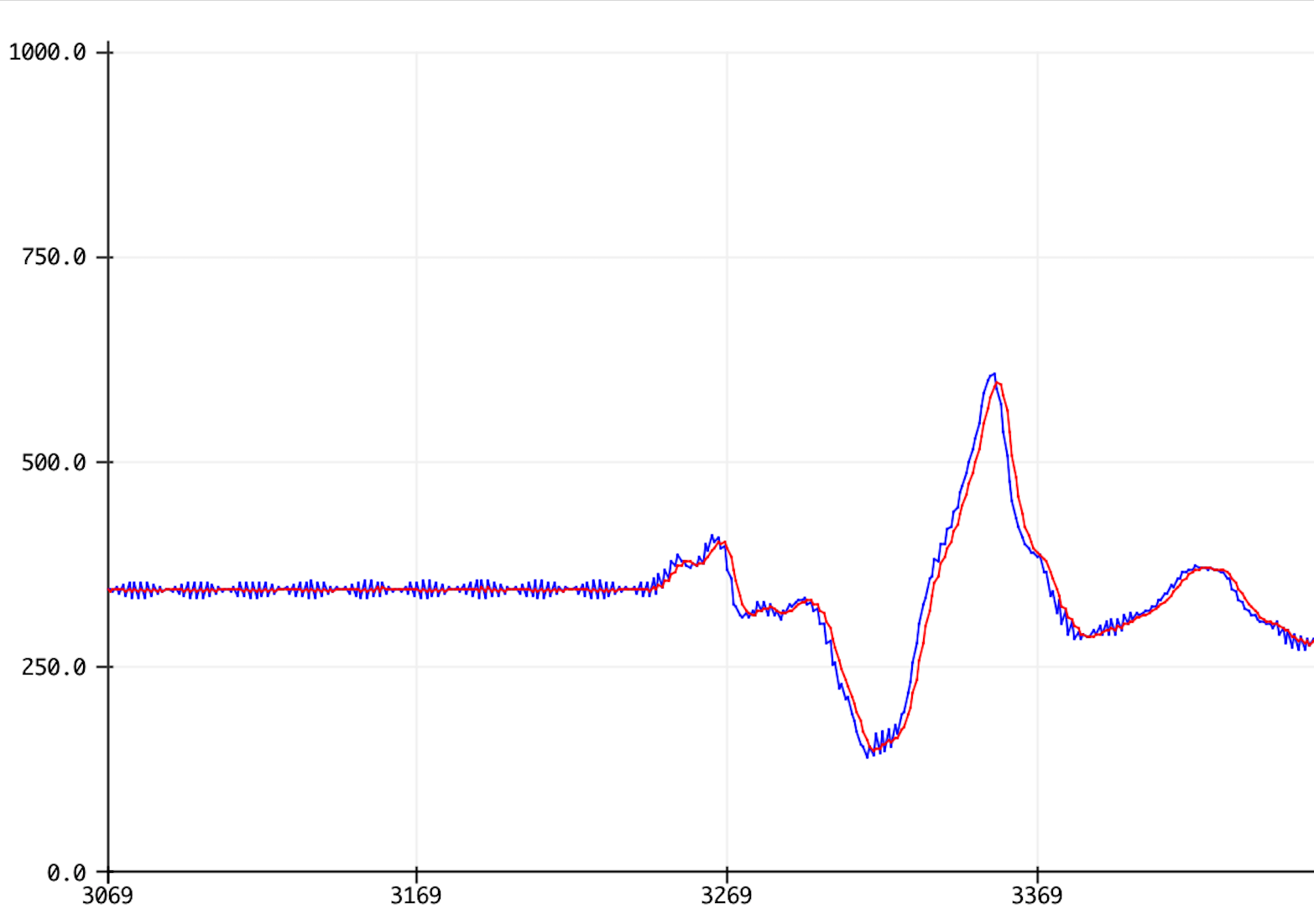
Serial Monitor output: the raw signal in blue, moving average in red.
The blue signal is the raw sensor output, with noise present. When the sensor value isn’t changing, there are high frequency signal components present. The red filtered signal, however, is free of the noise.
How the Code Works
The code keeps track of the sum of the five most recent readings in a variable called SUM. The five most recent readings themselves are in an array called READINGS, so that the oldest one can be accessed and removed from the sum when a new one arrives.
When a new reading arrives, it is added to the sum and the index (position in the array) is increased by one. The modulus operator (%) is used to wrap the index back to zero if the index exceeds the window size, since the modulus operator returns the integer remainder of one number divided by another.
Double-check the Window Size
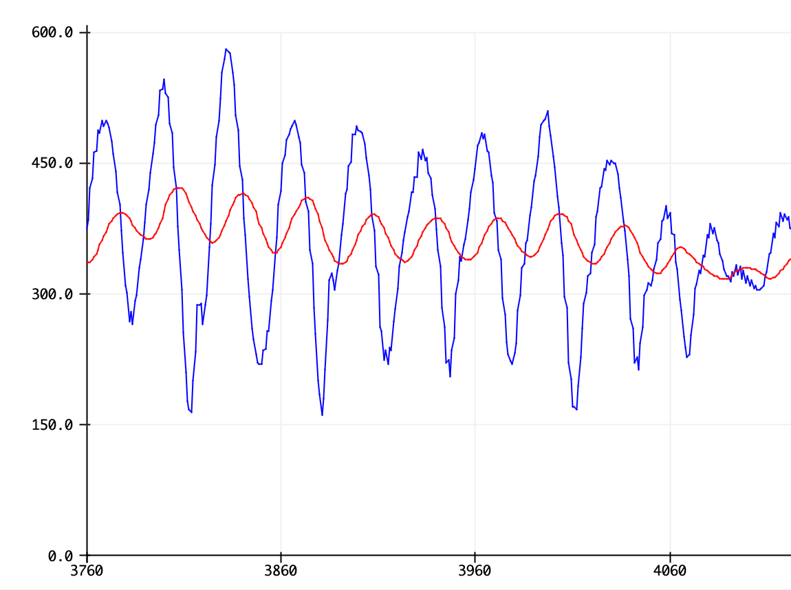
Notice that as a result of the calculation, the filtered signal lags slightly behind the raw input signal. If the window size is too large, this effect can become noticeable. The filtered signal will lag far behind the raw signal, and too much information will be lost from the signal, as shown below with a window size of 50.
When the window size is too large, the filtered signal lags noticeably behind the raw signal, and critical information is lost. The peaks of the filtered signal are much smaller than the peaks of the raw signal. Even if the noise is removed, critical information was also removed.