Learn how to use an Arduino to build and control a switched-mode power supply.
- In this tutorial, we will use our Arduino as a control circuit for a switched-mode power supply. A switched-mode power supply (SMPS) is an electronic circuit that converts the power using switching devices that are turned ON and OFF at high frequencies. The high efficiency of an SMPS makes them popular for use in computers and other sensitive electronics.
How a Switched-Mode Power Supply Works
A basic AC-DC SMPS consists of:
- Input rectifier and filter
- Transformer
- Output rectifier and filter
- Feedback and control circuit
In order to use an Arduino in this task, we can use PWM outputs of the board to control the output voltage. Pulse width modulation (PWM) is a common technique used to vary the width of pulses in a train of pulses.
PWM pins are used in many applications, including dimming an LED, providing variable speed control for motors, and more. Most importantly they are used to provide an analog output, providing an analog voltage between 0% and 100% if the digital output is filtered. On the Arduino UNO board, digital pins 3, 5, 6, 9, 10, and 11 are PWM pins.
The output of the circuit will be +30VDC and -30VDC. Further voltage adjustments require additional voltage regulators and potentiometers.
First, we will begin by stepping down voltage from mains and converting it to DC voltage via a rectifier circuit.
Required Hardware
Transformer and Rectifier Circuit
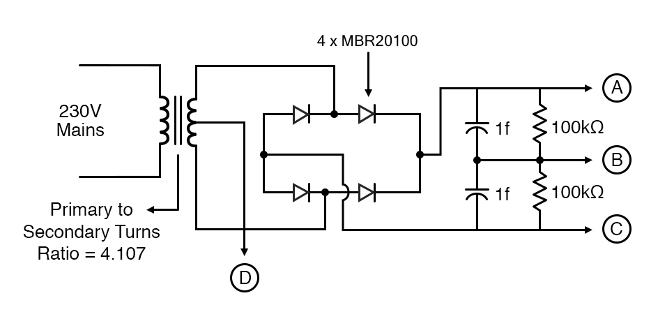
- Transformer (Primary to Secondary turns ratio 4.107)
- 4 x MBR20100 Schottky diodes
- 2 x 1F Capacitors
- 2 x 100kΩ resistors
+30V Output Circuit
- 2 x Fuse 13A
- 3.3Ω resistor
- 2 x 10uF Capacitors
- LM317 Regulator IC
- LM143 Op-amp
- Tip 147 Darlington transistor
- 1N4007 diode
- 100kΩ resistor
- 10kΩ resistor
- 80kΩ preset
For -30V Output Circuit
- Tip 142 Darlington transistor
- 3.3Ω resistor
- 2 x 10uF capacitors
- LM143 Op-amp
- LM337 voltage regulator IC
- 100k Ω resistor
- 1N4007 diode
- 90kΩ preset
- 10kΩ resistor
Software
Choosing a Transformer
Our very first step to building this power supply is choosing a transformer. Our power supply output is 30V DC and -30V DC symmetrically, max 10A both. So we will use a transformer with a primary-to-secondary turns ratio of 4.107, which will be able to supply 40V AC and max 15A to each of the secondary control circuits.
Designing the Rectifier Circuit
A rectifier circuit converts AC voltage to DC. So, our rectifier circuit converts our 40V AC to DC to get us close to the format of output we need. A very basic rectifier circuit consists of four diodes; here we will be using MBR20100 Schottky diodes. These diodes are widely used in SMPSs, reverse battery protection, converters, and more.
Rectifier circuit diagram
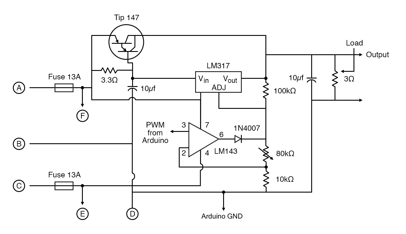
Designing the Control Circuits
Our +30V DC control circuit is built around the LM143 op-amp, a TIP142 Darlington transistor, an LM317 regulator IC, and an Arduino UNO.
First, we apply our positive voltage from the rectifier circuit to the Tip 147 transistor. It is a PNP-complementary power Darlington transistor often used in linear and switching industrial equipment.
We need to apply the center tape of the transformer generally ground for governing collector voltage of the transistor.
Now, we come across one of the most important components in this circuit: the LM143 op-amp. The main reason I chose this op-amp is that it features an operation +/- 40V complete input overvoltage protection with comparable currents.
We apply the PWM output from Arduino as a non-inverting input to the op-amp. With the GND pin, the Arduino is connected to the center tape of the transformer and also used as an inverting input. Further, we apply +40V and -40V from the rectifier circuit to V+ and V- of the op-amp, respectively. The output from the op-amp is then used as a reference voltage by the LM317.
The calculations here are simple enough.
We use an adjustable R2 resistance and R1 as 100kΩ. So, at the output, we get our desired variable +30V DC output. Further, we have used 10µF capacitors at input and output as decoupling capacitors to address input noise and output transients.
The controls circuit diagram
Circuit for +30V DC
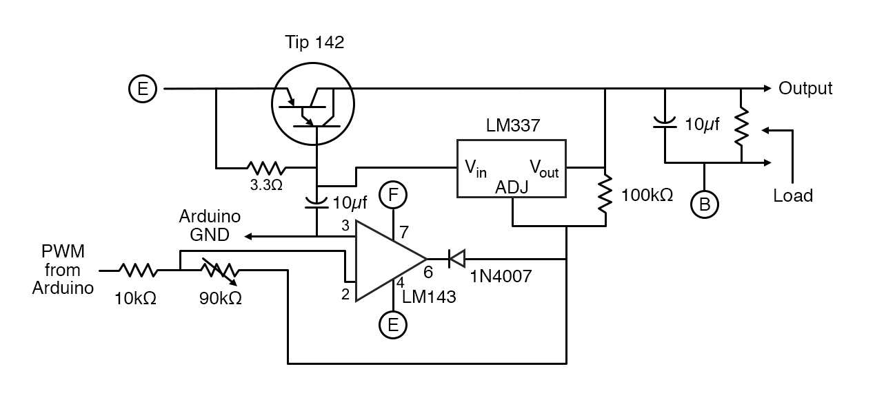
In order to get a -30V DC output, we have to provide PWM output from the Arduino as an inverting input and GND from Arduino to the non-inverting input of the op-amp. This allows our whole adjusting voltage to the LM317 and our final output to be inverted.
As the circuit is governed by negative voltage now, we use complementary components like LM 317 which is a negative adjustable regulator and Tip 142 which is NPN Darlington power transistor.
Circuit for -30V DC
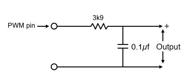
To note, we are using 13 A fuses to protect our components and load and low pass filters for PWM input to the circuit.
Arduino provides analog to digital (DAC) converters on the board to convert the input voltage to a digital form, However, they don't provide a digital to analog (DAC) converter, so we need to design a simple RC low pass filter which will convert our PWM signal to a voltage proportional to duty cycle.
We can see here that two of the most important components in our control circuits are governed by the PWM output of the Arduino and we get our desired symmetric +30V DC and -30V DC at the output with a maximum 10A of current.
SMPS Code
As we need to send messages to control power supply by computer, we need to use standard Firmata code. It is a library that consists of a set of rules that is needed for communication with hardware and smartphones, computers and tablets. You can find the code as a downloadable file.