Build your own Arduino-based radio using an Arduino, Nokia 5110 LCD Module, and KT0803 I2C FM Transmitter Module.
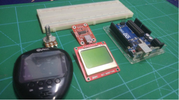
In this article, I will walk you through how to build an FM Transmitter using an Arduino Uno, Nokia 5110 LCD Module, and an I2C-based FM transmitter module board.
The final product can transmit your voice or music through a frequency modulation between 70MHz to 108MHz. The FM module we’re using comes with a 20-bit ADC audio chip which is basically used for digital signal and DSP core.
The FM transmitter output is amplified by an RF power amplifier and brought out to an antenna through an RF out pin. It operates between 1.6 V to 3.6 V and also it is fully compatible with different microcontrollers.
A Quick Note on Legalities
In most countries, it is illegal to build a personal radio station which covers a large area or to build and sell FM transmitters without a license. As I am writing this in reference to using it in the United States, I checked the Federal Communications Commission’s website for guidelines, which laid out requirements for me to follow, including the max range my transmitter can extend (200 feet).
Before building this transmitter or using an antenna to extend the reach, check for the free-to-use FM bands according to your country and make sure you’re obeying your country’s laws.
This tutorial is for creating an FM transmitter for personal use ONLY!
What is a KT0803K?
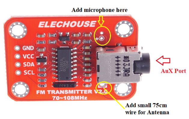
The KT0803K device is designed to process high fidelity stereo audio signals and transmit modulated FM signal over a short range. This module is basically designed for audio interfaces, especially for microphones or audio signal cables. We can also modify the audio signal input for amplitude adjustment and tune the microphone sensitivity since we can also add a microphone in this module.
Key Specifications
- I2C interface 5V TTL compatible
- Arduino plug and play
- Onboard MIC
- VCC Input: 3.0V to 5.0V
A small antenna can be connected with this module (any metal line about 75cm can serve as an antenna).
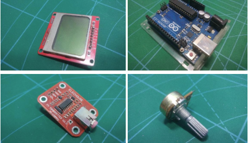
Wiring the Project
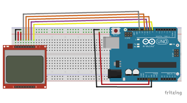
Wire up everything as shown below in the Fritzing diagram.
Arduino | Nokia 5110 LCD |
|---|
GND | GND |
D13 | SCK |
D11 | DIN |
D10 | CE |
D9 | DC |
D8 | RST |
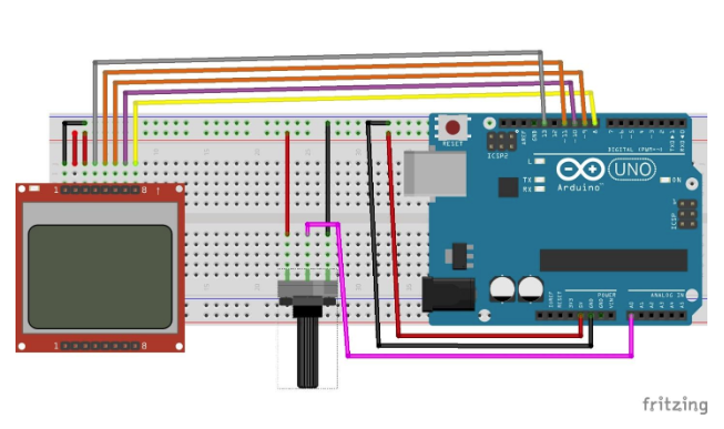
After completing these connections, add the potentiometer to A0 pin as shown below.
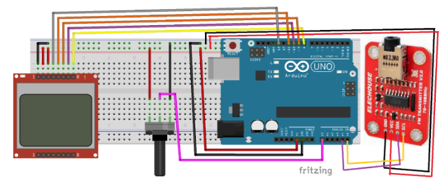
Arduino | FM Module |
|---|
GND | GND |
5V | VCC |
SDA | A4 |
SCL | A5 |
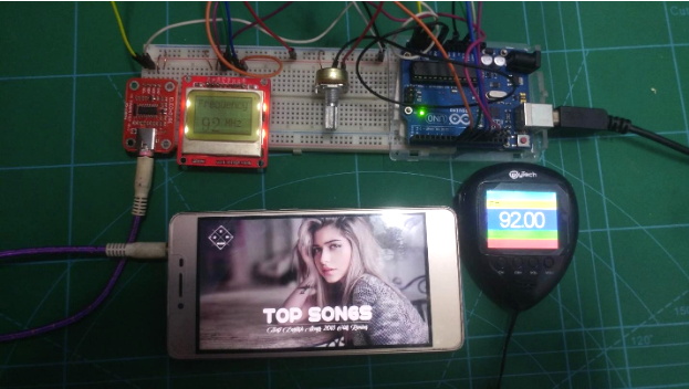
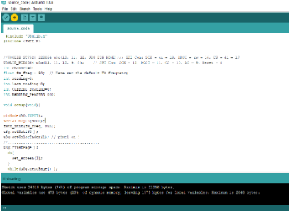
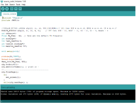
The final wired project should look something like the diagram above. Once the wiring is done, upload the code below.
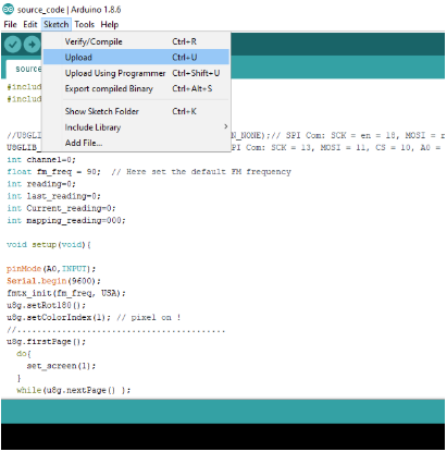
Source code
#include "U8glib.h"
#include <FMTX.h>
//U8GLIB_ST7920_128X64 u8g(13, 11, 12, U8G_PIN_NONE);// SPI Com: SCK = en = 18, MOSI = rw = 16, CS = di = 17
U8GLIB_PCD8544 u8g(13, 11, 10, 9, 8); // SPI Com: SCK = 13, MOSI = 11, CS = 10, A0 = 9, Reset = 8
int channel=0;
float fm_freq = 90; // Here set the default FM frequency
int reading=0;
int last_reading=0;
int Current_reading=0;
int mapping_reading=000;
void setup(void){
pinMode(A0,INPUT);
Serial.begin(9600);
fmtx_init(fm_freq, USA);
u8g.setRot180();
u8g.setColorIndex(1); // pixel on !
//..........................................
u8g.firstPage();
do{
set_screen(1);
}
while(u8g.nextPage() );
delay(1000);
//....................
u8g.firstPage();
do{
set_screen(0);
}
while(u8g.nextPage() );
delay(1000);
Clear();
//..........
u8g.firstPage();
do{
intro();
}
while(u8g.nextPage() );
delay(2500);
u8g.firstPage();
do{
intro2();
}
while(u8g.nextPage() );
delay(2500);
Clear();
//..........................................
}
// Reading Any Tunning change here.
void Analog_pin_read(){
channel=mapping_reading;
Current_reading=channel;
fmtx_set_freq(channel);
}
void set_screen(int i){
u8g.setColorIndex(i); // pixel on !
for (int x_axis=0;x_axis<84;x_axis++){
for (int y_axis=0;y_axis<44;y_axis++){
u8g.drawPixel(x_axis,y_axis);
}
}
}
void Clear(void){
u8g .setFont(u8g_font_04b_03);
u8g.setFontRefHeightExtendedText();
u8g.setDefaultForegroundColor();
u8g.setFontPosTop();
}
void intro(void){
u8g.setColorIndex(1);
u8g.drawFrame(0,0,83,47);
u8g .setFont(u8g_font_osr18);
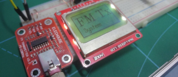
u8g.drawStr( 5, 25, "FM Tx ");
u8g .setFont(u8g_font_tpss);
u8g.drawStr( 5, 40, " System");
}
void intro2(void){
u8g.setColorIndex(1);
u8g.drawFrame(0,0,83,47);
u8g .setFont(u8g_font_04b_03);
u8g.drawStr( 2, 7, "Build Your FM station! ");
u8g.drawStr( 2, 15, "Modify the frequency");
u8g.drawStr( 2, 26, "By Ammar");
u8g.drawStr( 2, 38, "Maker.PRO");
}
//change frequency value On lcd here
void number(int value){
u8g.setColorIndex(1);
u8g.drawFrame(0,0,83,47);
u8g .setFont(u8g_font_unifont);
u8g.drawStr( 5, 15, "Frequency ");
u8g .setFont(u8g_font_osr18);
u8g.setPrintPos(10,45);
u8g.println(value,DEC);
u8g .setFont(u8g_font_unifont);
u8g.drawStr( 45, 38, "MHz ");
}
void loop(){
reading=analogRead(A0);
mapping_reading=map(reading,0,1023,90,100);
mapping_reading=constrain(mapping_reading,90,100);
if( mapping_reading!= Current_reading){
Clear();
Analog_pin_read();
u8g.firstPage();
do{
number(channel);
}
while(u8g.nextPage() );
delay(100);
}
}