Learn to design an Arduino-based buck/boost converter, a DC-DC converter found in portable electronic devices.
DC-DC converters are widely used in portable electronic devices like mobile phones and laptops and are primarily powered with batteries. These applications consist of many sub-circuits which provide different voltage levels to different modules of the system. DC-DC converters also make solar harvesting easier and there are such converters that maximize energy harvesting for solar cells, wind turbines, and more. They are known as power optimizers.
There is a more efficient version of DC-DC converters — switch-mode DC-DC converters. Here, the switch-mode technique is used to convert the DC voltage to varying voltage, then rectifying and filtering is done to get the desired voltage. This approach is cheaper and more efficient and it is widely used in almost all portable DC devices and it comes integrated into some chips for direct utilization.
There are two main types of switch-mode DC-DC converters that are most often used:
- Buck converters
- Boost converters
A buck converter steps down the voltage level while stepping up the current and a boost converter steps up the voltage level while stepping down the current. Let's take a look at the two types of converters to better understand what each one can do.
What is a Buck Converter?
A buck converter is a switch-mode power supply that consists of a diode with an energy storage element which can be a capacitor or an inductor.
Step down conversion can also be done by linear voltage regulators. These regulators step down the input voltage to a stable desired output voltage by dissipating extra power in the form of heat. Therefore, this approach is not as efficient when compared to switch mode buck converters.
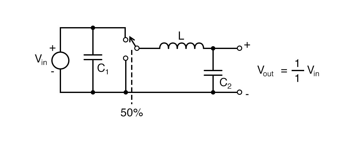
A simple buck converter circuit.
The above-presented circuit is a simple buck converter circuit in which the switch continuously switches between Vin and ground at a rapid rate with 50% duty cycle, so circuit spends equal time in both levels. The output voltage is equal to half the input voltage. Thus, this is categorized as a switch mode supply because we are getting half the power by switching at a 50% duty cycle.
Besides the components being non-ideal, the circuit is 100% efficient. This circuit is called a synchronous buck converter and it is the modified version of the simple buck converter circuit which is presented below:
A synchronous buck converter circuit.
What is a Boost Converter?
A boost converter is also a class of switch-mode power supply that steps up the voltage from its input to load. It also has a similar arrangement as a buck converter circuit consisting of a diode and an energy storage element but it is slightly different.
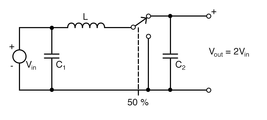
A basic boost converter circuit.
The above-presented circuit is very similar to the synchronous buck converter circuit. The only difference is that the energy storing device is now connected before the oscillating switch which increases the voltage at the output end, but the current is reduced at the same time.
In the above circuit, when the switch is open, the inductor is charged with the energy with the help of the generated magnetic field. Now when the switch is closed, the current is reduced because load impedance is higher and the magnetic field is no longer there. So, a series connection is made that causes a higher voltage at the output.
Note that if the switching is fast enough, the inductor will never get out of the stored energy and we get a higher voltage at the output. The capacitor in parallel with the load is used to get charged with the series voltage generated so that it can feed the load when the switch is open for a longer time. The diode prevents the current from the capacitor to flow backward.
Arduino-based Buck and Boost Converters
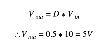
From the circuits we have discussed so far, we are clear that we have to turn switch ON-OFF using PWM signals of the Arduino controller board. For a buck converter, the output voltage is the product of the input voltage and duty cycle. For example, if the duty cycle of the switch is 50% and Vin is 10V then:
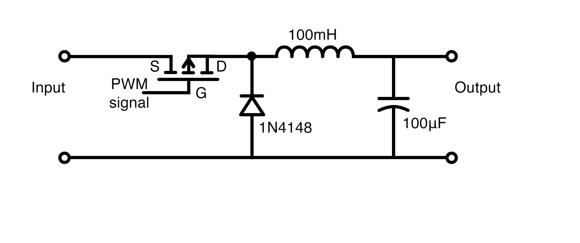
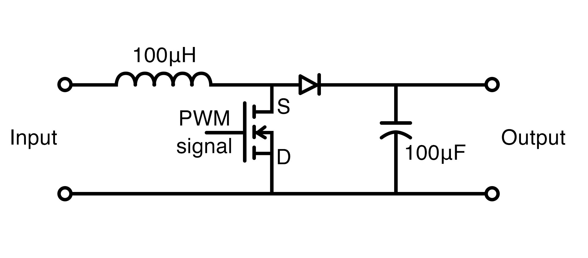
So we can adjust the duty cycle of PWM pulses to adjust the output voltage and therefore we can directly apply the PWM signals from Arduino to the MOSFET that will act as a switch.
Buck converter circuit diagram.
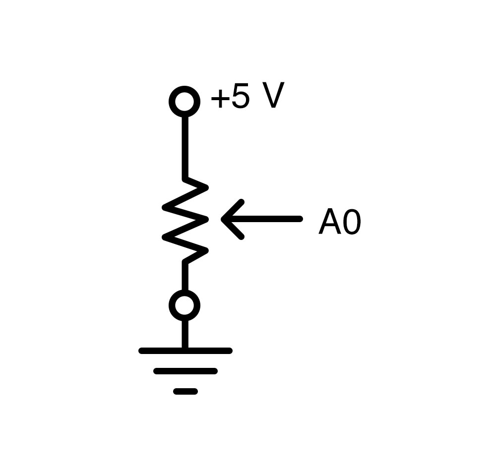
We can also utilize a potentiometer with Arduino to adjust our output voltage. Our analogwrite() code will read the values from 1 to 244 in digital form. We get this digital format from the ADC converter of Arduino. Here, 1 stands for the lowest duty cycle (i.e., 0%) and 244 represents the maximum duty cycle (i.e., 100%).
The ADC converter of the Arduino.
Similarly, the circuit for an Arduino-based boost converter is given below. Here the equation is quite different:
Vout = 1/(1-D) *Vin
Arduino-based boost converter circuit.
Note: Load impedance must be around 100 ohms for these circuits and if it’s higher, inductors and capacitors will be quickly discharged and might ruin the output waveforms.
Arduino Buck/Boost Converter Code
int potentiometer = A0; //From the main potentiometer
int PWM = 3;


void setup() {
  pinMode(potentiometer, INPUT);
  pinMode(PWM, OUTPUT);
  TCCR2B = TCCR2B & B11111000 | B00000001;    // pin 3 and 11 PWM frequency of 31372.55 Hz
}

void loop() {

  float voltage = analogRead(potentiometer);
  int VALUE = map(voltage,0,1024,0,254);
  analogWrite(PWM,VALUE);

}