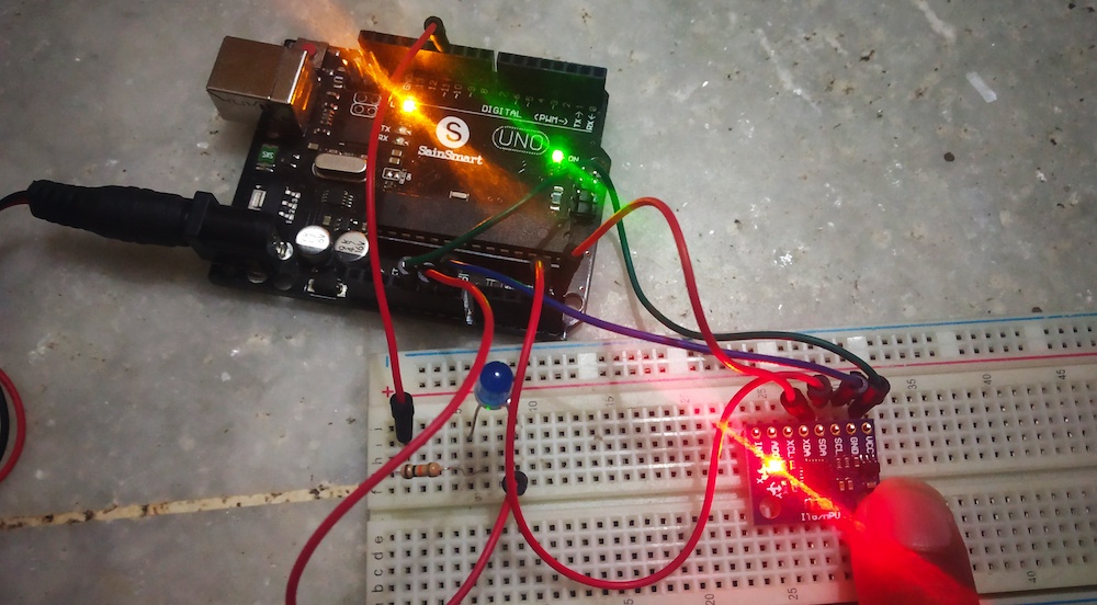
Learn how you can create a simple fall detector with an Arduino UNO, an MPU6050, and the right algorithm!
Fall detection is a major challenge in the public healthcare domain. Falls for the elderly can be especially serious, as they can lead to serious health issues. Making a system to alert when a fall occurs is helpful, as it provides peace of mind to both the wearer and their loved ones.
Nowadays, fall detectors are commonly included in smartwatches, wearable fitness trackers, and other types of wearables. Fall detection can also be done by a surveillance camera, also known as a computer-vision-based fall detection system. There are several kinds of fall detection methods and the algorithm each uses is what makes them unique and accurate.
In most fall situations, the body leans to the side and touches the ground with high acceleration. So, an algorithm must detect a fall in these situations when there is a rapid change of position in a very short amount of time.
Commonly, fall detection systems use a gyroscope and an accelerometer. A gyroscope is used to determine an orientation and an accelerometer provides the information about the angular parameter as three-axis data. But we also need to decide a threshold so that the system can differentiate between a fall and normal activity.
The circuit we discuss in this tutorial is built around an Arduino UNO and an MPU6050 accelerometer and gyroscope breakout module. We will also try to send the SOS message via a Wi-Fi module. First of all, we need to decide on an algorithm.
Required Materials
- Arduino UNO
- MPU6050 accelerometer and gyroscope breakout module
- Arduino IDE (Software)
Making an Algorithm
We will go with the threshold-based detection system and check whether a parameter is above a certain threshold value within a time interval. In a fall situation, there is a large change in acceleration within a split second and then after the fall, the person lies still for some time, showing no change in orientation. Knowing these details allows us to create our algorithm.
First, we will collect data from the accelerometer and then calculate the acceleration magnitude. Acceleration magnitude tells us about how quickly velocity changes while acceleration tells us the rate of change in velocity, so we need acceleration magnitude here.
The above equation is of the magnitude of acceleration and the three values ax, ay, and az are the acceleration of X-, Y-, and Z-axis respectively as per data collected.
After calculating the acceleration magnitude, we need to know if its value breaks the lower threshold. The lower threshold is the minimum threshold in the range decided by us and the value gradually increases up to the high threshold. Then we need to check that it breaks the high threshold in some milliseconds — let's say 500ms.
If all of these are detected as true conditions, then we need to check whether there is a change in orientation within 500ms and usually, it's true if the above conditions are true. After that, we check to see if orientation remains the same for some time. If yes, then there was a fall. There is a loop, meaning that if a condition is false at any stage, the process goes back to start and re-executes.
Note: There might be no orientation change in a fall but this algorithm requires the involvement of orientation change.
The Fall Detector Circuit
The circuit is built around an Arduino UNO and an MPU6050 accelerometer and gyroscope breakout module. For collecting data, we rely on the MPU6050 module to give analog input to the Arduino UNO. The MPU6050 module provides six values as output, three values of an accelerometer, and three values of a gyroscope. It is a sensor-based on MEMS (microelectro mechanical systems) technology and uses I2C protocol for communication. Sensors like this are widely used in smartphones, robotics, 3D modeling, UAVs, and more.
The MPU6050 consists of a three-axis gyroscope, a three-axis accelerometer, a digital motion processor, and an on-chip temperature sensor. It’s a complete package and if we connect a three-axis magnetometer via the I2C connection we get a complete nine-axis motion fusion output.
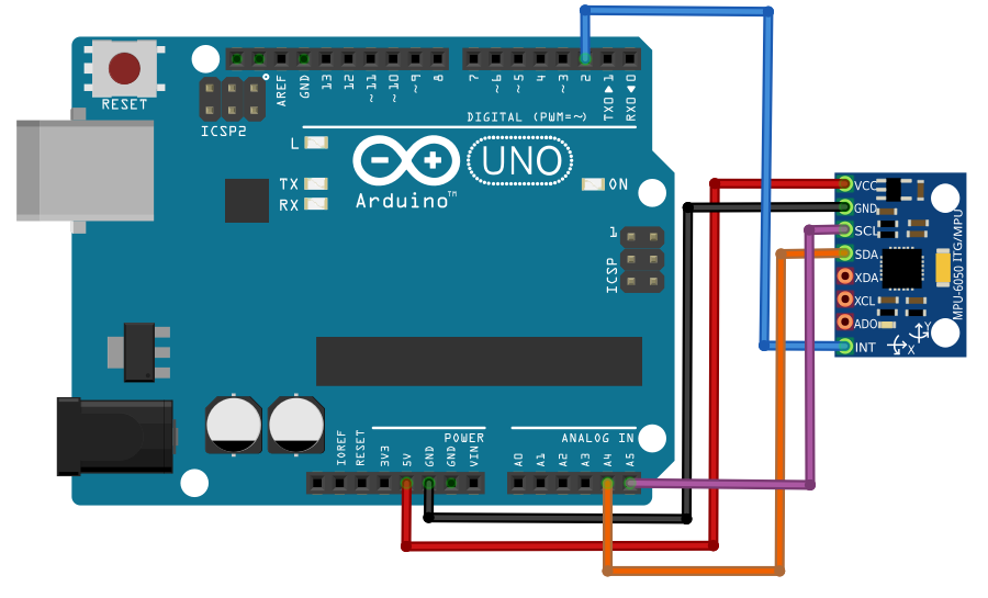
Connecting the Arduino UNO and the MPU6050.
The interfacing is quite simple. We are using A4 and A5 pins of the Arduino UNO for data reception.
Further, digital pin 11 of the Arduino is the output pin and it gets high on the fall detection. One can use this pin and connect it with an ESP8266 Wi-Fi module. Next thing to perform will be making a recipe on IFTTT (if this then that) for a button (button recipe) and then checking the hardware.
Source Code
The code is based on the algorithm stated above and follows seven steps:
- Collect data from the module
- Calculate magnitude of acceleration.
- Check if the value of magnitude breaks the lower threshold. If false, return to Step 1.
- Check if the magnitude breaks the higher threshold in 0.5 seconds. If false, return to Step 1.
- Check for change in orientation within 0.5 seconds. If false, return to Step 1.
- Check if orientation remains same for 10 seconds. If false, return to Step 1.
- Change the output pin as HIGH on the detection of fall (if all of the above steps are resulted as true).
The full code can be found at a zip file at the end of the article.
With the code running, we have successfully built our fall detector using an Arduino UNO and MPU6050 module. The interfacing is very simple and we follow our algorithm in the code.
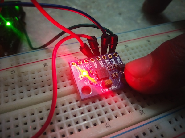
The MPU6050 working in the build.
You can use this circuit for various purposes. Although this was built as a fall detector, I have also personally used this circuit to release a parachute in the case of freefall but there I needed to change the algorithm and timings by eliminating the last step of checking the orientation continuation. In such cases, the timing differs and the acceleration magnitude is also a bit high while the object is rising in the air when used in weather-balloon-type weather stations thus deciding the threshold becomes the main task.


