Learn the design of buck-boost converters with feedback which allow for adjustable and stable power supplies.
A buck-boost converter is a switch-mode DC-DC converter that provides an output voltage greater than or less than the input voltage. The arrangement of a buck-boost converter circuit is similar to that of the buck converter and boost converter circuits; in fact, it is a combination of both these circuits.
In a previous article, I discussed the design of an Arduino-based buck and boost converter circuit. This article serves to show you how to design when you need an adjustable and stable power supply using feedback.
There are two different topologies of the buck-boost converter:
- Inverting buck-boost converter
- Non-inverting topology
In this tutorial, we look at both the inverting and non-inverting topology of a buck-boost converter and design an Arduino-based buck-boost converter with feedback.
Inverting Topology
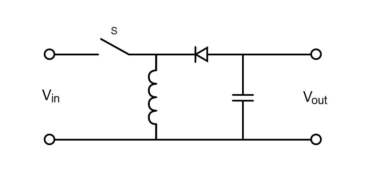
In inverting topology, the output voltage is the reverse polarity of the input voltage.
Circuit diagram of inverting topology.
Being similar in its arrangement, it also works in such a way that the output voltage is adjustable based on the duty cycle of the switch.
Here, when the switch is in the ON state, the input voltage connected to the inductor charges it up and supplies energy to the load.
In the OFF state, the inductor is directly connected to the load and energy to the load is provided by the two energy storage elements in the circuit. Hence, our DC component is directly proportional to the duty cycle of switching but inverted.
Note that there is a bit of a complication in this circuit because there is no connection to ground. However, there is no point considering this limitation if you’re working with isolated, independent power sources like batteries.
Non-inverting Topology
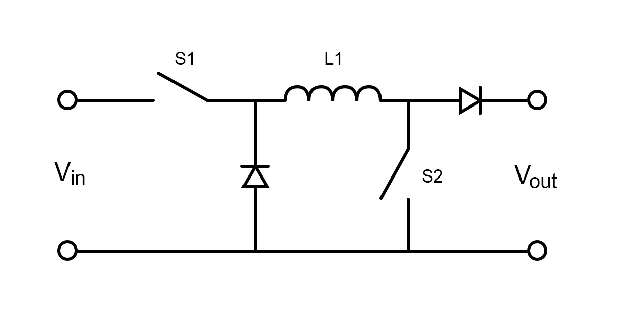
Here, the output voltage is not inverted but can be adjusted in every way, meaning it can be decreased or increased. This is the generalized topology that is very widely used and will be used by us for a very interesting circuit ahead. Here, the arrangement is the combination of the buck converter and boost converter circuits.
Circuit diagram of non-inverting topology.
When S1 is closed and S2 is switched, the circuit operates as a boost converter. When S2 is open keeping S1 oscillating, we get a buck converter circuit. Thus, we can increase or decrease our output voltage according to our requirements.
There is another version of a buck-boost converter known as a flyback converter. Here, the inductor is split to form a transformer. So, voltage ratios of primary and secondary windings of the transformer are multiplied, but there is one more advantage of this circuit: isolation (more technically, galvanic isolation). So a flyback converter adjusts the output voltage providing an additional feature of isolation. This circuit is used in very common low power supplies like phone chargers.
Circuit diagram of a flyback converter.
The inner working of this circuit is quite simple. When the switch is ON, the primary coil is charged and the capacitor supplies the energy to the load. When the switch is in OFF, EMF is induced in the secondary coils and the diode is now conducting allowing energy to load.
Designing the Buck-boost Converter With Feedback Circuit
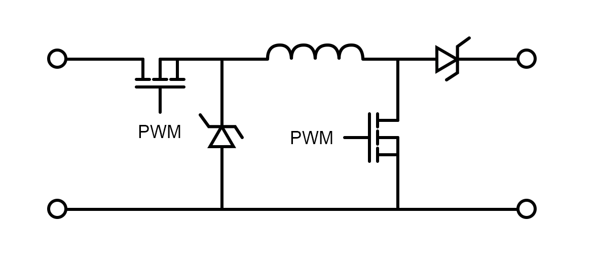
The simple buck-boost converter circuit controlled by PWM signals is very simple and similar to that of boost converter and buck converter circuits.
Here when S1 is shorted, the circuit works as a boost converter providing the output voltage of 1/(1-D)*Vin and when S2 is shorted, the circuit works as a buck converter with an output voltage of D*Vin.
The buck-boost converter circuit controlled by PWM signals.
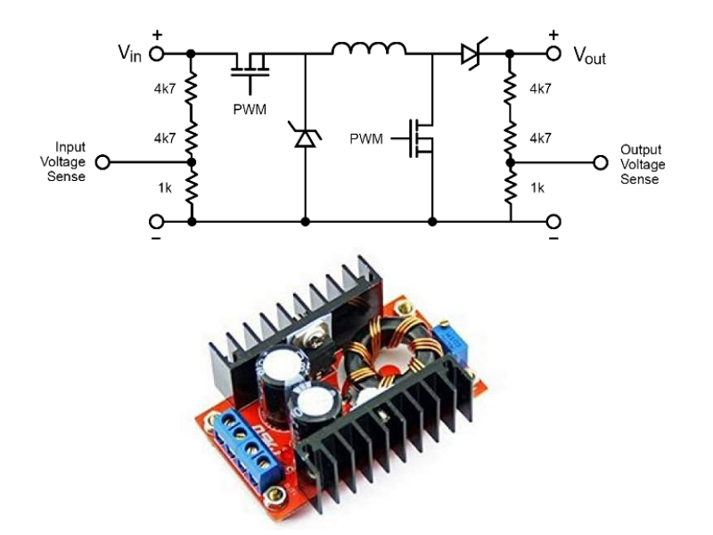
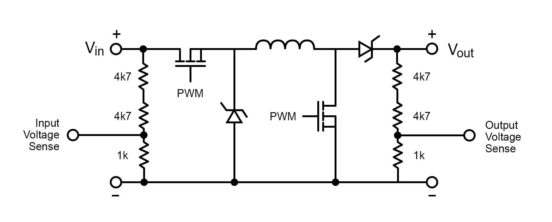
By adding feedback from the output and input terminals, we can make an automatic buck-boost converter circuit that automatically adjusts the output voltage keeping it stable. In addition to the previous circuit, we have to use a voltage divider for input and output voltage sensing and to provide this data to the analog input pins of the Arduino.
The circuit after adding feedback from the output/input terminals and a voltage divider for input/output voltage sensing.
For PWM signal input, we use Arduino pins 5 and 6 supplying PWM signals to the power MOSFET. We have to hack into the PWM and adjust the frequency configuration of Timer0 to say 62.5 kHz PWM.
Input voltage data goes to Arduino analog pin 0 and the output voltage goes to analog pin 2. Also, note that we use Schottky diodes to minimize diode losses; 1N5817 Schottky diodes are perfect for such applications.
Thus we have made an automatic buck-boost converter that automatically stabilizes the output voltage with the help of feedback-based input and output voltage sensing.
Full Arduino Automatic Buck-boost Converter Code
#define vin_pin A1
#define output_voltage_sense A2
#define input_voltage_sense A0
#define boost_pin 5
#define buck_pin 6
int raw_vin=0, raw_vout=0, raw_iout=0;
float Vout_max=13.0, Iout_max=1.0, Vout_min=11.1, Iout_min=0.1,Vin_thresold=10.5;
float Iout_sense;
float Vout_sense;
float Vin_sense;
uint8_t duty_cycle = 25;
String mode="";
bool startup=true;
unsigned int count=0;
void setup() {
  // put your setup code here, to run once:
Serial.begin(115200);

 TCCR0B = TCCR0B & 0b11111000 | 0x01;
 analogWrite(buck_pin,255);
analogWrite(boost_pin,0);
}

void loop() {
  if(Serial.available()) {
    String data = Serial.readString();
    Vout_max = data.toInt();
    Vout_max = Vout_max/10;
    Serial.print("Vout_max= ");
    Serial.println(Vout_max);
  }

  for(int i=0;i<10;i++) {
raw_iout += analogRead(input_voltage_sense)-513;
raw_vin += analogRead(vin_pin);
raw_vout += analogRead(output_voltage_sense);

  }
  raw_iout=raw_iout/10;
  raw_vout=raw_vout/10;
  raw_vin=raw_vin/10;
  Iout_sense=float(raw_iout)*0.0586;
  Vout_sense=float(raw_vout)*0.046;
  Vin_sense=float(raw_vin)*0.046;
if(count>100) {
Serial.print("Vin= ");Serial.println(Vin_sense);
Serial.print("Vout= ");Serial.println(Vout_sense);
Serial.print("Iout= ");Serial.println(Iout_sense);
Serial.print("Duty cycle= ");Serial.println(duty_cycle);
Serial.print("Converter MODE : ");Serial.println(mode);
count=0;
}
if(startup==false) {
regulate(Iout_sense, Vin_sense, Vout_sense);
auto_cutoff(Iout_sense,Vin_sense, Vout_sense);
}
else {
  soft_start();
}
delay(600);
count++;
}

void regulate(float Iout, float Vin, float Vout) {
if(Vout_max<Vin) {
  mode="";
  mode="Buck mode";
  analogWrite(boost_pin,0);
  if((Iout<Iout_max && Iout>Iout_min) && (Vout<Vout_max)) {
    if(duty_cycle<250) {
    duty_cycle+=2;
    }
    analogWrite(buck_pin,255-duty_cycle);
  }
  else if((Iout>Iout_max) || (Vout>Vout_max)) {
    if(duty_cycle>2) {
    duty_cycle-=2;
    }
    analogWrite(buck_pin,255-duty_cycle);
  }

}
else if(Vout_max>Vin) {
  mode="";
  mode="Boost mode";
  analogWrite(buck_pin,0);
  if((Iout<Iout_max) && (Vout<Vout_max)) {
    if(duty_cycle<220) {
    duty_cycle+=2;
    }
    analogWrite(boost_pin,duty_cycle);
  }
  else if((Iout>Iout_max) || (Vout>Vout_max)) {
    if(duty_cycle>4) {
    duty_cycle-=2;
    }
    analogWrite(boost_pin,duty_cycle);
  }

}
}


void auto_cutoff(float Iout,float Vin, float Vout){
  if((Vout>=Vout_max) && (Iout<Iout_min) || (Vin<Vin_thresold)) {
    analogWrite(boost_pin,0);
    analogWrite(buck_pin,255);
    Serial.println("Charging Completed.");
    delay(64000);
  }
}

void soft_start() {
  if(Vout_sense<=Vout_min) {
  regulate(Iout_sense, Vin_sense, Vout_sense);
Serial.print("Vin= ");Serial.println(Vin_sense);
Serial.print("Vout= ");Serial.println(Vout_sense);
Serial.print("Iout= ");Serial.println(Iout_sense);
Serial.print("Duty cycle= ");Serial.println(duty_cycle);
Serial.print("Converter MODE : ");Serial.println(mode);
Serial.println("Soft Start Activated");
  delay(64000);
  }
  else {
  startup=false;
  }
}