Discover how to create long-distance serial communication between two or more Arduino boards.
We know that Arduino has several built-in buses for fast data transfer. For example, displays usually use the SPI bus. Various kinds of sensors are often connected via the I2C bus. There is also the popular UART, which is often used with a USB interface to exchange data with a computer. But all of these methods have a serious drawback: they do not work at large distances.
Imagine a situation where we need to collect data from sensors on the roof of our house, and, depending on the sensors’ testimony, switch a relay in our basement. How can we make it possible? We’ll definitely need a powerful, noise-resistant interface — one that can be used for years. The RS-485 module can do this job smoothly.
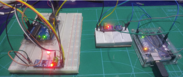
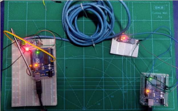
In this article, we will connect two Arduino boards using a long cable and RS-485 interface.
What is an RS-485?
RS-485 is a serial interface which is the predecessor of the RS232. This module gained fame because of the COM ports of old computers that just worked on the RS232 interface.
The maximum range of the RS-485 module is 1200 meters, which means we can expand our signal up to 1.2km. If there are special amplifiers on the line, it can extend even further. The transmission speed over such a long wire will be about 60 kb/s, which is a relatively good speed for transmitting the sensor’s data.
A twisted pair cable is used for the RS-485’s cable. This cable is still used in Ethernet lines, making it easily available. To transfer data at a distance of more than 500 meters, you will need a shielded twisted pair. Thirty-two devices can be connected to one cable, but at the same time only one device can transfer data.
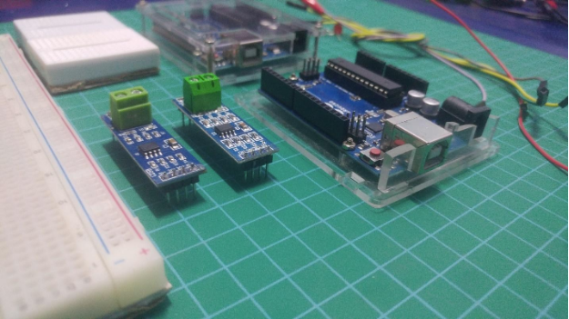
Required Hardware
- 2 x Arduino
- 2 x RS-485 Module
- Breadboard
- Some wires
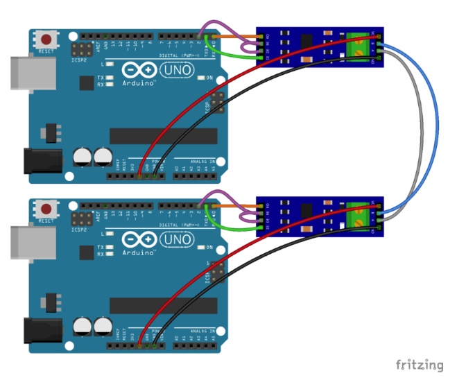
Schematics for Connecting Two Arduinos Using an RS-485
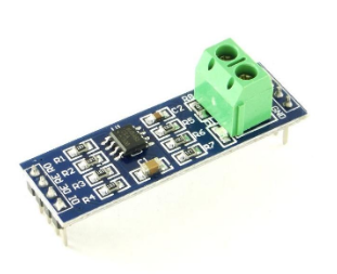
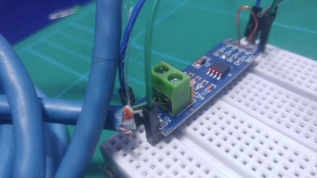
In order to connect two Arduino boards via the RS-485 interface, we need a special module. Typically, such modules use the popular MAX485 chip.
Cable connection with a length of several meters.
Note: In the figure above, wires A and B are straight. This will suffice if the distance is small. In the case of a cable connection with a length of several meters, you have to use a twisted pair!
The Receiver and Transmitter Program for RS-485
As we have already noted, if several devices are connected to the line only one device can transmit data at a time. We need to somehow inform all other devices that we are ready for transmission, and they must remain silent and listen. This can be done with the help of contacts DE and RE.
Let's write two programs. One will broadcast the text “ping” every 500 ms. The other will listen to the broadcast and, when receiving the text “ping”, flash LED #13.
Transmitter Program
#define SerialTxControl 2 // contact # 2 will switch receiver / transmitter mode
#define RS485Transmit HIGH
#define RS485Receive LOW

void setup (void) {
    Serial.begin (9600); // set the serial port to 9600baud speed
    pinMode (SerialTxControl, OUTPUT);
    digitalWrite (SerialTxControl, RS485Transmit); // put the device into transmitter mode
}

void loop (void) {
    Serial.print ("ping"); // send text
    delay (500);
}
Receiver Program
#define SerialTxControl 2
#define RS485Transmit HIGH
#define RS485Receive LOW

char buffer [100];
byte state = 0;

void setup (void) {
    Serial.begin (9600);
    pinMode (13, OUTPUT);
    pinMode (SerialTxControl, OUTPUT);
    digitalWrite (SerialTxControl, RS485Receive); // put the device into receiver mode
}

void loop (void) {
    int i = 0;
    if (Serial.available ()) {// if any data came to the port
        delay (5); // wait a bit for the entire data packet to be accepted by the port
        while (Serial.available ()) {
            buffer [i ++] = Serial.read (); // read data and write it to the buffer
        }
    }
    if (i> 0) {// if there is something in the buffer
        buffer [i ++] = '\ 0'; // convert the buffer contents to a string by adding a null character
        if (strcmp (buffer, "ping")) {// if the accepted string is equal to the ping text
            digitalWrite (13, state); // blink LED
            state =! state;
        }
    }
}
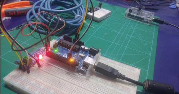
Load both of these programs onto each Arduino board. If everything is assembled correctly and connected to the power supply, the LED connected to pin 13 will start blinking on the second board.
Conclusion
The RS-485 has been used since the late 90s in a variety of industrial systems where data needs to be transmitted over long distances, in the presence of electromagnetic interference. As a rule, the RS-485 interface is used together with specialized protocols, such as ModBus or DMX512.