Learn how to use an RCWL-0516 motion detection sensor and build a Proximity Sensor with an Arduino!
In this tutorial we will be building a motion alarm system. The RCWL-0516 is a motion detection sensor. It can detect motion through doppler microwave technology through walls or other materials. It will get triggered not only by people but also by any other moving objects.
What is Doppler Radar?
Based on the Doppler effect, Doppler radar works by bouncing a microwave signal off a desired target and analyzing how the object's motion has altered the frequency of the returned signal. The variation in the received signal can also help measure the target’s velocity with respect to the radar.
Doppler Radar is effectively used in a variety of applications including aviation, meteorology, radar guns, healthcare, and military.
The sensor we are using in this project —the RCWL-0615 — contains both the transmitter and receiver thereby enabling doppler radar.
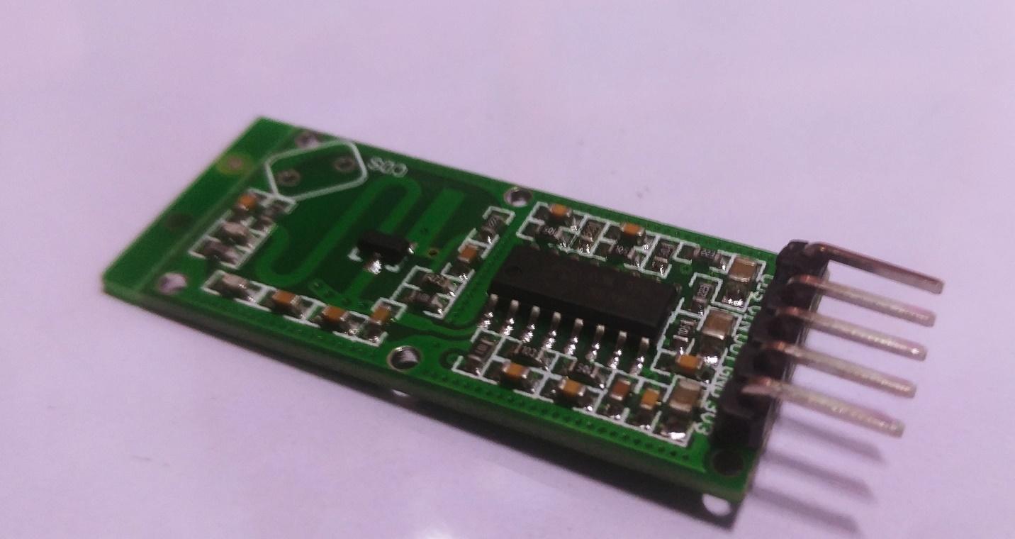
The RCWL-0615 Microwave Proximity Sensor
The RCWL-0615 sensor module is an alternative to the common PIR motion sensors which are widely used in burglar alarms and security lights. PIR sensors use black body sniff mechanism, which means that it checks for emitted heat from human bodies. The RCWL-0516 utilizes Doppler radar technology to detect moving objects. It operates at about 3.2GHz and uses the RCWL-9196 processing chip.
The RCWL-0516 emits microwaves and analyses the reflected waves to check for any changes. These sensors can detect moving objects through walls and other materials and have a sensitivity range of seven meters. They are usually less expensive and less prone to errors. When motion is detected, the sensor’s TTL-level output (OUT) pin will switch from LOW (0 V) to HIGH (3.3 V) for a finite time (2 to 3 s) before returning to its idle (LOW) state.
RCWL-0615 Microwave Proximity Sensor
RCWL-0615 Key Features
- Transmit power: 20 mW (minimum)/30 mW (max)
- Voltage input: 4–28 VDC
- Sensing Distance: 5–7 m
- Frequency of sensor: ~3.2 GHz
RCWL-0615 Pinout
- VIN — 4V - 28V DC power supply input
- CDS — Sensor disable input (low = disable) (For LDR sensors)
- GND — Ground
- 3volt— DC output (100 mA maximum)
- OUTPUT — HIGH /LOW(3.3 V) (according to the motion detection)
Now that we’re familiar with the sensor we’re using and how the technology works, let’s dive into the build!
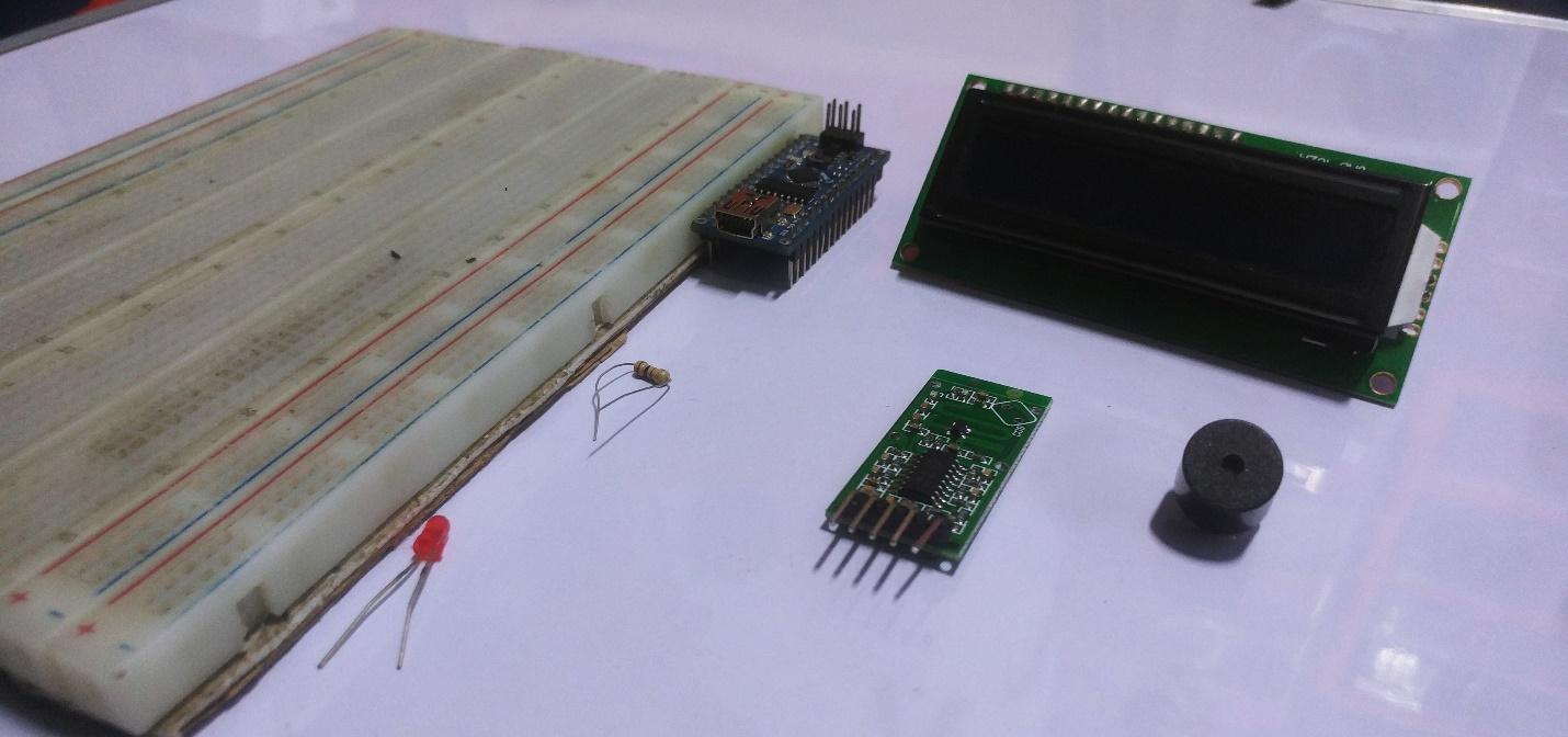
Required Hardware
- Arduino Nano
- Breadboard
- Jumper wires
- RCWL-0516
- Character LCD 16 X2 I2C
- Buzzer X 1
- LED X 1
- 220ohm resistor X 1
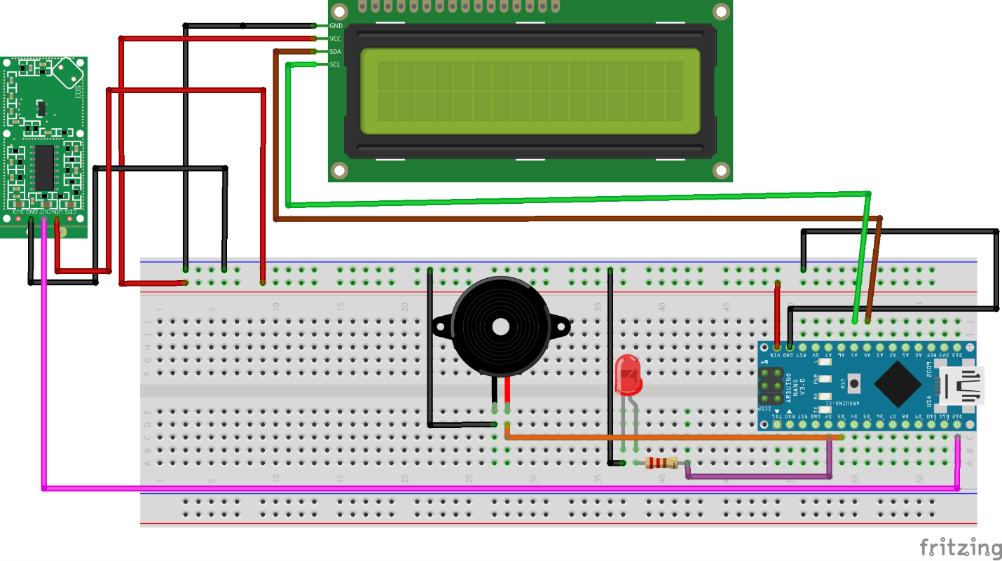
Wiring the Hardware
Wire up the Arduino to the RCWL-0516, character LCD, buzzer, and LED as shown in the diagram below.
| Arduino Pin Number |
|---|
LED | 2 |
Content | 3 |
Arduino Analog IO | Character LCD |
|---|
A5 | SCL |
A4 | SDA |
Arduino Nano | RCWL-0516 |
|---|
GND | GND |
5V | VIN |
D2 | OUT |
Pin 3V3 on the RCWL-0516 is an output pin. The CDS pin lets you add an LDR (light dependent resistor) to the board, which allows for operation in low power mode so that the sensor only activates in the dark.
After wiring up everything, double-check the connections and then upload the source code.
Source Code
#include <Wire.h>
#include <LiquidCrystal_I2C.h>
// Set the LCD address to 0x27 for a 16 chars and 2 line display
LiquidCrystal_I2C lcd(0x27, 16, 2);
int Sensor = 12; //Input Pin
int LED = 3; // Led pin for Indication
int Buzzer =2;
int flg = 0; //Change detection flag
void setup() {
Serial.begin(9600);
// initialize the LCD
lcd.begin();
lcd.clear();
lcd.print("...MAKER.PRO...");
delay(3000);
// Turn on the blacklight and print a message.
lcd.backlight();
pinMode (Sensor, INPUT); //Define Pin as input
pinMode (Buzzer, OUTPUT); //Led as OUTPUT
pinMode (LED, OUTPUT); //Led as OUTPUT
Serial.println("Waiting for motion");
}
void loop() {
int val = digitalRead(Sensor); //Read Pin as input
if((val > 0) && (flg==0))
{
digitalWrite(LED, HIGH);
digitalWrite(Buzzer, HIGH);
lcd.clear();
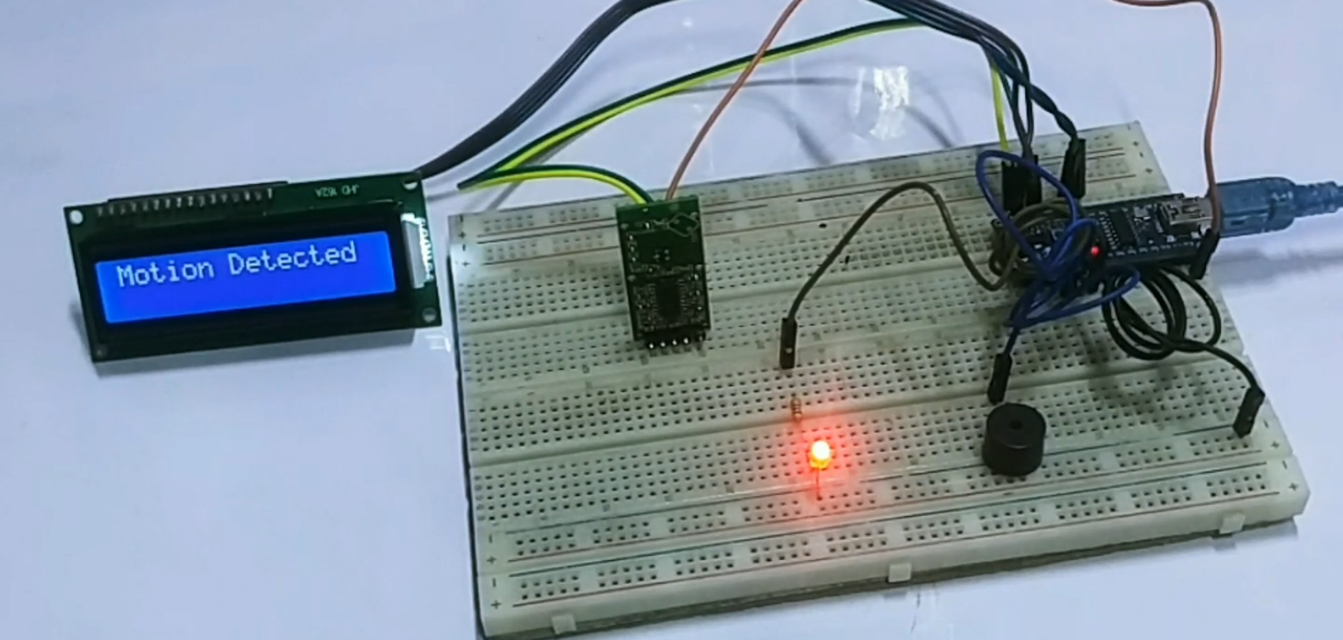
Serial.println("Motion Detected");
lcd.print("Motion Detected");
flg = 1;
}
if(val == 0)
{
digitalWrite(LED, LOW);
digitalWrite(Buzzer, LOW);
lcd.clear();
Serial.println("NO Motion");
lcd.print("NO Motion ");
flg = 0;
}
delay(100);
}