Learn how to add a circuit to calibrate your antenna with your Arduino for maximum signal accuracy!
Antennas need to be calibrated properly to get maximum signal exposure and minimum noise level, and different types of antennas require different amounts of calibration. For television, one can easily calibrate an antenna themselves (yet not accurately because the frequency band is very high). For microwave bands, however, it is very important to point the antenna in azimuth as precisely as possible in a given direction and also elevate the antenna accurately.
Azimuth and Elevation Values for Antennas
Azimuth and elevation values are measures used to identify the satellite or any broadcaster.
The azimuth value tells us in what direction to face the antenna while elevation tells us about how high up in the sky antenna should face. An azimuth value ranges from 0 to 360 degrees. Here, north is 0 degrees, and when you change the direction to the east, it will be 90 degrees and so on. When you return to facing north, it will read 360 degrees.
The elevation value generally ranges from 0 to 180 degrees. When the satellite is overhead, the value will be 90 degrees and when at the horizon, the value will be 0 degrees. So, it is easy to point at the sky with the help of these both values.
We will try to design a circuit using Arduino to display these values on a screen.
The Antenna Calibration Circuit
The approach to building the circuit is very simple.
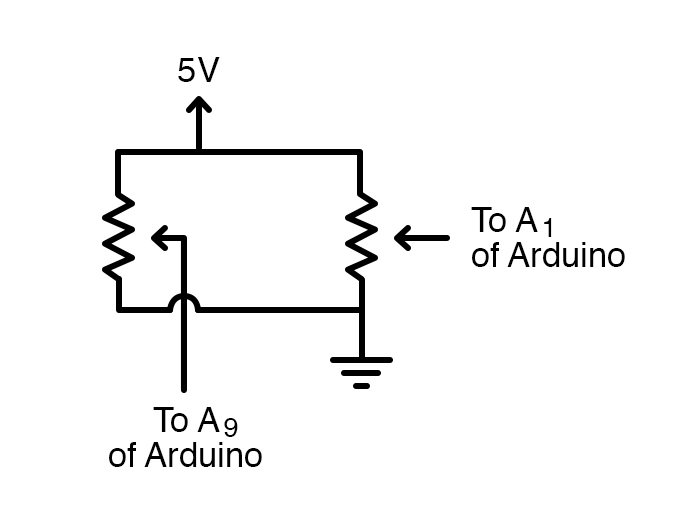
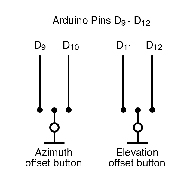
If we use potentiometers for the elevation and azimuth values, it would be very convenient to then read the analog values by the Arduino board. So, it is simple to measure the azimuth and elevation values using a potentiometer and then have the Arduino convert the measurements into degrees. The remaining offsets are provided by pushbuttons, making our circuit portable.
Next, we will interface a 16 x 2 LCD screen to Arduino for displaying the values. Now, the accuracy can be set to 1, 0.5 or 0.1 degrees. Here the azimuth range is from 0 to 360 degrees and elevation range is from -90 to 270 degrees.
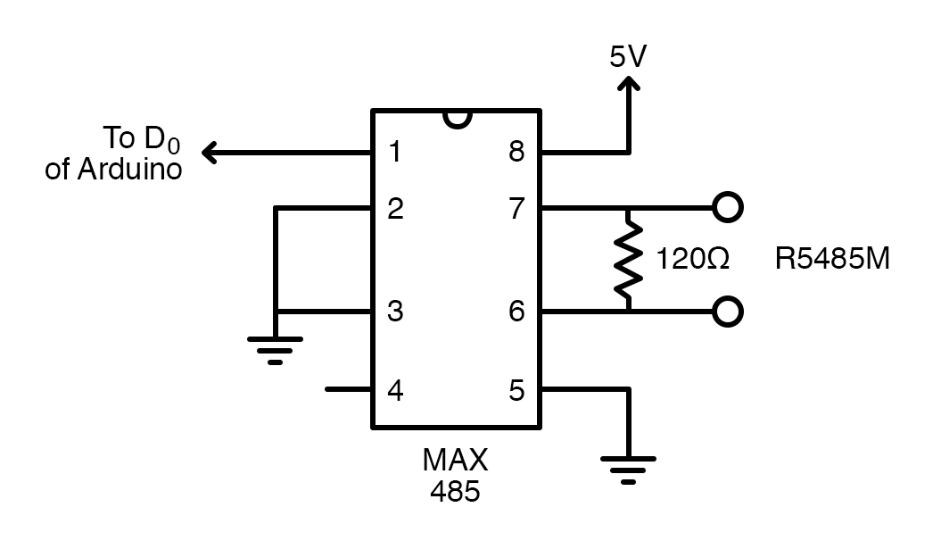
When the antenna is outside, we can use a long cable between the antenna sensors and our circuit via an RS485 module. We will use a separate cable for azimuth and elevation values and feed it into the display unit.
Utilizing a MAX485 IC
We are using a MAX485 IC as a low power RS485 trans-receiver. It consists of one driver and one receiver. The receiver input gives a logic high output if the input is open circuit. Pin 6 and 7 of the IC are the inputs and pin 1 is UART receiver pin. We give two independent inputs to IC and R0 is connected to D0 of our Arduino. The rest of the display and offset circuit remains the same.
Antenna Calibration Code
For the code, we will first initialize the offset inputs — the resolutions for both elevation and azimuth values. Then we will try to convert both the values to degrees and then finally display the converted values on the LCD screen.
#include <LiquidCrystal.h> // include the library code:
#include <EEPROM.h>
#include <stdlib.h>

const int offazup = 3;  // pin for change az offset
const int offazdn = 4;  // pin for change az offset
const int offelup = 5;  // pin for change el offset
const int offeldn = 6;  // pin for change el offset

// button variables
int stateoffazup = 1;  // buttonstate az offset
int stateoffazdn = 1;  // buttonstate
int stateoffelup = 1;  // buttonstate el offset
int stateoffeldn = 1;  // buttonstate

// frame variables
unsigned char del = 0; // delimiter character
unsigned char frameend = 0; // end of frame character
unsigned char ello = 0; // elevation low byte
unsigned char elhi = 0; // elevation high byte
unsigned char azlo = 0; // azimuth low byte
unsigned char azhi = 0; // azimuth high byte

//display resolution az; MAKE YOUR OWN CHOISE
//int azr = 1; // display resolution 1 degree
//int azr = 2; // display resolution .5 degree
//int azr = 5; // display resolution .2 degree
int azr = 10; // display resolution .1 degree

//display resolution el; MAKE YOUR OWN CHOISE
//int elr = 1; // display resolution 1 degree
//int elr = 2; // display resolution .5 degree
//int elr = 5; // display resolution .2 degree
int elr = 10; // display resolution .1 degree

// calculation and display variables
int el = 0; // elevation value in decimal format
float elg = 0; // el in degrees
int elgi = 0; // el in integer format (10 times el)
float elgearfactor = 1.0; // FILL IN YOUR CORRECTION FACTOR FOR THE ELEVATION GEAR

int az = 0; // azimuth value in decimal format
float azg = 0; // az in degrees
int azgi= 0; // az in integer format
float azgearfactor = 1.0; // e.g. 1.764; // FILL IN YOUR CORRECTION FACTOR FOR THE AZIMUTH GEAR

int offsetaz = 0; // offset for azimuth
int offsetel = 0; // offset for elevation

// EEPROM addresses
#define EEPROM_ADDR_STATUS 0
#define EEPROM_ADDR_OFFSET_AZ 1
#define EEPROM_ADDR_OFFSET_EL 3

// general variables needed in program
int d = 0; // timer delay

LiquidCrystal lcd(12, 11, 10, 9, 8, 7);// initialize the library with the numbers of the interface pins

void setup()
{
  lcd.begin(16, 2); // set up the LCD's number of columns and rows
  Serial.begin(9600);  // opens serial port, sets data rate to 9600 bps
  pinMode(offazup, INPUT_PULLUP); // set pin to input and enable pullup resistor
  pinMode(offazdn, INPUT_PULLUP);
  pinMode(offelup, INPUT_PULLUP);
  pinMode(offeldn, INPUT_PULLUP);

  if (1 == EEPROM.read (EEPROM_ADDR_STATUS))
  {
    char* p_mem = (char*)(&offsetaz);
    p_mem [0] = EEPROM.read (EEPROM_ADDR_OFFSET_AZ);
    p_mem [1] = EEPROM.read (EEPROM_ADDR_OFFSET_AZ + 1);
    p_mem = (char*)(&offsetel);
    p_mem [0] = EEPROM.read (EEPROM_ADDR_OFFSET_EL);
    p_mem [1] = EEPROM.read (EEPROM_ADDR_OFFSET_EL + 1);
  }
}

// Main program
void loop()
{
  readstatebuttons();// changing offset?
  d = 300;
  while (stateoffazup == LOW || stateoffazdn == LOW || stateoffelup == LOW || stateoffeldn == LOW) {
    offsetcorrection();
  }

  if (Serial.available() > 15)
  {
    del = Serial.read();
    Serial.println (del);
    while (del != 0xD0 && del != 0xD1 && del != 0xD2 ) {
      del = Serial.read();
    }; // search for 0xD0, 0xD1 or 0xD2 hex in data

    if (del == 0xD0) // header az frame
    {
      del = 0;
      readframe();
      if (frameend == 0x13 && elhi == 0 && ello == 0) // check frame
      {
        transformaz();
        displayaz();
      }
    }

    if (del == 0xD1)  // header of el frame
    {
      del = 0;
      readframe();
      if (frameend == 0x13 && azhi == 0 && azlo == 0) //check frame
      {
        transformel();
        displayel();
      }
    }

    if (del == 0xD2)  // header of az/el frame
    {
      del = 0;
      readframe();
      if (frameend == 0x13) //end of frame character
      {
        transformaz();
        displayaz();
        transformel();
        displayel();
      }
    }
  }
}

void readframe()  // read frame
{
  elhi = Serial.read();
  ello = Serial.read();
  azhi = Serial.read();
  azlo = Serial.read();
  frameend = Serial.read();
}

void transformaz()  // transform azimuth info to degrees
{
  az = azhi * 256 + azlo; // az information in decimal format
//az = 4092 - az; // for reverse scaling
  azg =(float(az) * 360 * azgearfactor)/4093; // transformation to degrees
  azg = azr* azg;
  azg = round (azg);
  azg = azg/azr;
  azg = 10 * azg;
  azgi = azg;
}

void transformel()  // transform elevation info to degrees
{
  el = elhi * 256 + ello;
//el = 4092 - el; // for reverse scaling
  elg = (float(el) * 360 * elgearfactor)/4093;

  elg = elr * elg;
  elg = round (elg);
  elg = elg/elr;
  elg = 10 * elg;
  elgi = elg;

  }

void displayaz() // display azimuth value
{
  int azgd; // az value for display purposes
  char buffer [17]; //buffer for dislay a line on LCD

  azgd = azgi + (offsetaz)/azr;

//Serial.println (offsetaz); // for test purposes

  if (azgd >= 3600) {
    azgd = azgd - 3600;
  }
  else if (azgd < 0) {
    azgd = 3600 + azgd; // az has always a positive value
  }

  int upper_part = azgd/10;
  int lower_part = azgd%10;

//Serial.println(upper_part); // for test purposes
//Serial.println(lower_part); // for test purposes

  if (azr <=1) {
    sprintf (buffer, "Azimuth   %3d ", upper_part);
  }
  else {
    sprintf (buffer, "Azimuth   %3d.%1d ", upper_part, lower_part);
  }

  lcd.setCursor (0, 0);
  lcd.print (buffer);
}

void displayel()  // display elevation value
{
  int elgd; // el value for display purposes
  int neg = 0; // boolean for display negative el values
  char buffer [17]; //buffer for dislay a line on LCD

  elgd = elgi + offsetel/elr; // display value corrected with offset

if (elgd >= 3600) {
    elgd = elgd - 3600;
  }
  else if (elgd < 0) {
    elgd = 3600 + elgd; // el has now always a positive value
  }

if (elgd > 2700) {
    elgd = 3600 - elgd;
    neg = 1;
  }

  int upper_part = elgd/10;
  int lower_part = elgd % 10;

//Serial.println(upper_part); // for test purposes
//Serial.println(lower_part); // for test purposes

 if (neg==1) {
  if (elr <=1){
    sprintf (buffer, "Elevation -%2d", upper_part);
  }
  else {
    sprintf (buffer, "Elevation -%2d.%1d ", upper_part, lower_part);
  }
    neg = 0;
 }
 else {
  if (elr <=1){
   sprintf (buffer, "Elevation %3d", upper_part);
  }
  else {
    sprintf (buffer, "Elevation %3d.%1d ", upper_part, lower_part);
  }

 }
  lcd.setCursor (0, 1);
  lcd.print (buffer);
}

void readstatebuttons()
{
  stateoffazup = digitalRead(offazup);
  stateoffazdn = digitalRead(offazdn);
  stateoffelup = digitalRead(offelup);
  stateoffeldn = digitalRead(offeldn);
}

void offsetcorrection()
{
  if (stateoffazup == LOW)
  {
    offsetaz = offsetaz + 10;
    displayaz();
    delay (d);
    if (d > 30) {
      d = d - 30;
    }
  }
  if (stateoffazdn == LOW)
  {
    offsetaz = offsetaz - 10;
    displayaz();
    delay (d);
    if (d > 30) {
      d = d - 30;
    }
  }
  if (stateoffelup == LOW)
  {
    offsetel = offsetel + 10;
    displayel();
    delay (d);
    if (d > 30) {
      d = d - 30;
    }
  }
  if (stateoffeldn == LOW)
  {
    offsetel = offsetel - 10;
    displayel();
    delay (d);
    if (d > 30) {
      d = d - 30;
    }
  }

//offsetaz = 0; //useful for filling offset zeros in EEPROM
//offsetel = 0; //useful for filling offset zeros in EEPROM

  // writing offset data to EEPROM
  EEPROM.write (EEPROM_ADDR_STATUS, 1);
  char* p_mem = (char*)(&offsetaz);
  EEPROM.write (EEPROM_ADDR_OFFSET_AZ  , p_mem [0]);
  EEPROM.write (EEPROM_ADDR_OFFSET_AZ + 1, p_mem [1]);
  p_mem = (char*)(&offsetel);
  EEPROM.write (EEPROM_ADDR_OFFSET_EL  , p_mem [0]);
  EEPROM.write (EEPROM_ADDR_OFFSET_EL + 1, p_mem [1]);

  readstatebuttons();
}
This is a very simple and easy way to achieve results. We can also add a three-axis digital compass module, which can be attached to the antenna to easily track these values. An I2C extender board can be used for an extension to the antenna at the top.