Learn how to take your robot to the next level by adding object following capabilities with an ultrasonic sensor.
After making a line-following robot, making a robot that can avoid obstacles is usually one of the first projects recommended for both robotics enthusiasts and engineers-to-be. What if we wanted to combine these two ideas to make a robot follow a flat object?
Let me show you how to do that in this project!
Creating Object Focus With an Ultrasonic Sensor
Line follower robots usually equip color sensors to differentiate between the line they are following and the floor.
Obstacle avoiders utilize infrared or ultrasonic sensors to make sure there is nothing in front of them and keep traversing a preprogrammed course. However, focusing on a single object and calculating its trajectory is another kind of problem.
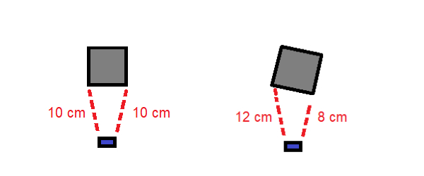
Attaching a transmitter to the object and a receiver on the follower is the usual solution, but we will only be using one ultrasonic sensor for a challenge. By having a servo motor sway the sensor side to side in a thirty-degree arc, we can measure the distance of an object from both viewable edges. Assuming we are following an object with a flat back side, we can know if an object is turning left or right by measuring these values against each other.
The object of interest (gray) turning right while the ultrasonic sensor (blue) measures edge distance.
With this information, we can instruct our robot to turn accordingly and avoid losing the target object.
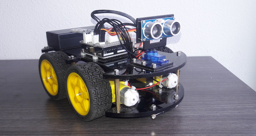
For this project, we will only need a four-wheeled robot with appropriate motor drivers, an Arduino Uno board, a micro servo motor, and an HC-SR04 ultrasonic sensor.
Setting up the Hardware
Since the difficult part of this project is the code, the hardware is relatively simple.
I used an Elegoo Smart Robot Car v3 for this project, but any four-wheel-drive robot car with a rotating ultrasonic sensor will work. You may have to tweak some parts of the sketch a bit, but I have marked them for convenience.
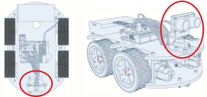
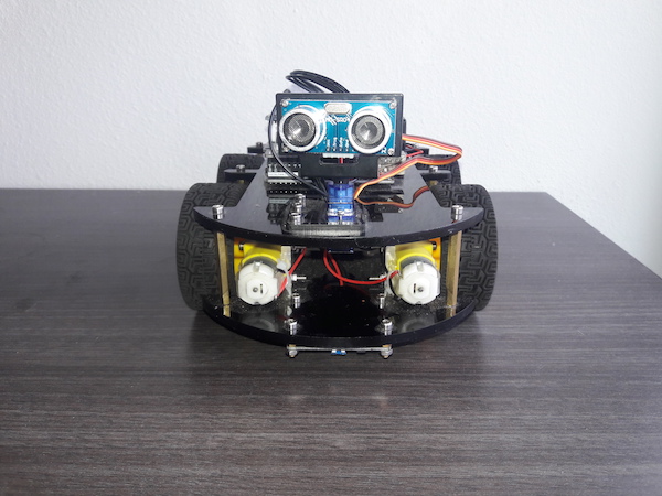
The ultrasonic sensor will be placed on the front of the robot. Take this into consideration if building your own robot from scratch.
Position of the ultrasonic sensor relative to the rest of the robot.
In order to make your robot work correctly, be sure to mount the ultrasonic sensor on the front of your robot.
Putting the Code in Arduino IDE
The bulk of this project is in the software, so be ready to get your hands dirty with the code.
The only library we will use is the Servo library built-in to the Arduino IDE. For a copy of the Follower Robot sketch, check out the GitHub repository. Now, let’s go over how the code works.
#include <Servo.h>  //servo library
Servo myservo;      // create servo object to control servo

//Ultrasonic sensor variables
int Echo = A4;
int Trig = A5;

//motor controller pins
#define ENA 5
#define ENB 6
#define IN1 7
#define IN2 8
#define IN3 9
#define IN4 11
#define carSpeed 150
#define carSpeed2 150
int rightDistance = 0, leftDistance = 0;
The first thing you will notice is the servo motor. This will be used to swivel the ultrasonic sensor. Next, you will see the pins I have assigned to the ultrasonic sensor. Analog 4 and 5 are used in this case, but if you are planning on using different pins make sure to change these. You can use digital pins if you would like.
I am using A4 and A5 because that is the default configuration for the Elegoo Car. The EN and IN pins are used to assign motor speed values and motor direction, respectively. If you are not using the same car as I am, you will need to change these values to fit your motors’ pins.
carSpeed(0-255) is the maximum analog value the motors will be given. carSpeed2 can be used to make the car turn faster or slower while retaining the same forward and backward carSpeed value. A larger carSpeed value will make your robot faster, but also consume more energy.
The two integers initialized in the last line store the distance in centimeters from the target to the ultrasonic sensor.
void forward(){
  analogWrite(ENA, carSpeed);
  analogWrite(ENB, carSpeed);
  digitalWrite(IN1, HIGH);
  digitalWrite(IN2, LOW);
  digitalWrite(IN3, LOW);
  digitalWrite(IN4, HIGH);
  Serial.println("Forward");
}

void back() {
  analogWrite(ENA, carSpeed);
  analogWrite(ENB, carSpeed);
  digitalWrite(IN1, LOW);
  digitalWrite(IN2, HIGH);
  digitalWrite(IN3, HIGH);
  digitalWrite(IN4, LOW);
  Serial.println("Back");
}
void left() {
  analogWrite(ENA, carSpeed2);
  analogWrite(ENB, carSpeed2);
  digitalWrite(IN1, LOW);
  digitalWrite(IN2, HIGH);
  digitalWrite(IN3, LOW);
  digitalWrite(IN4, HIGH);
  Serial.println("Left");
}
void right() {
  analogWrite(ENA, carSpeed2);
  analogWrite(ENB, carSpeed2);
  digitalWrite(IN1, HIGH);
  digitalWrite(IN2, LOW);
  digitalWrite(IN3, HIGH);
  digitalWrite(IN4, LOW);
  Serial.println("Right");
}
void stop() {
  digitalWrite(ENA, LOW);
  digitalWrite(ENB, LOW);
  Serial.println("Stop!");
}
There are five movement commands for this robot, forward(), back(), left(), right(), and stop().
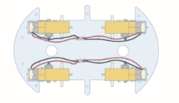
Each movement is in the format of forward() (pictured above), and moves the robot in the specified direction. Here, ENA and ENB, the front and back half of the robot, are commanded to move at carSpeed. IN1 and IN4, the left side motors’ direction pins, are commanded to turn counterclockwise with the HIGH value. IN2 and IN3, the right side motors’ direction pins, are commanded to turn clockwise. This allows our robot to move straight even though our motors are inverted.
If both sides of the motors moved in the same direction, our robot would simply spin in circles.
//Ultrasonic distance measurement method
int Distance_test() {
  digitalWrite(Trig, LOW);
  delayMicroseconds(2);
  digitalWrite(Trig, HIGH);
  delayMicroseconds(20);
  digitalWrite(Trig, LOW);
  float Fdistance = pulseIn(Echo, HIGH);
  Fdistance= Fdistance / 58;
  return (int)Fdistance;
}
This method sends out a pulse from the ultrasonic sensor. It then uses the speed of sound and the time the pulse took to return to calculate distance. This is one of the most common ways to use an ultrasonic sensor, so I will not go into more detail here.
void setup() {
  myservo.attach(3);  // attach servo on pin 3 to servo object
  Serial.begin(9600);
  pinMode(Echo, INPUT);
  pinMode(Trig, OUTPUT);
  pinMode(IN1, OUTPUT);
  pinMode(IN2, OUTPUT);
  pinMode(IN3, OUTPUT);
  pinMode(IN4, OUTPUT);
  pinMode(ENA, OUTPUT);
  pinMode(ENB, OUTPUT);
  stop();
}
In the setup method we make sure our sensor and motors are ready to go. stop() is used to make sure the motors stop moving before they receive any commands.
void loop() {

    myservo.write(60);  //setservo position to right side
    delay(200);
    rightDistance = Distance_test();

    myservo.write(120);  //setservo position to left side
    delay(200);
    leftDistance = Distance_test();


    if((rightDistance > 70)&&(leftDistance > 70)){
      stop();
    }else if((rightDistance >= 20) && (leftDistance >= 20)) {
      forward();
    }else if((rightDistance <= 10) && (leftDistance <= 10)) {
        back();
        delay(100);
    }else if(rightDistance - 3 > leftDistance) {
        left();
        delay(100);
    }else if(rightDistance + 3 < leftDistance) {
        right();
        delay(100);
    }else{
      stop();
    }

}
In loop(), we have our repeating code. First, we set our servo to sixty degrees, calculate the distance to the object, then move the servo sixty degrees to the left to do it again. Below that is our object-following logic. If there is nothing in front of the robot for seventy centimeters, it will stop moving until something is in front of it. This was done to prevent interference from walls or objects far away from the target object.
Our robot will try to stay ten centimeters behind the target object, moving forwards and backward depending on the target’s position. If either side is three centimeters further away than the other, the robot will turn in that direction to follow its predicted path.
Keep in mind that the sixty-degree arc for the ultrasonic sensor as well as the three-centimeter threshold for turning can be changed depending on the project. If your target object is long, you may benefit from having a wider arc and a smaller turning threshold. All that is left now is to test it out!
The Completed Robot
So did it work? Check out the video below of my finished project!