nRF24L01 radio transceiver provides very efficient and inexpensive way to establish communication.
nRF24l01 module is in fact a radio transceiver module and it operates on 2.4 GHz frequency. This module has the capability to send and receive data simultaneously and this can be used for your various IOT projects to create a wireless connection . By display it is a very small size module but it’s features are astonishing.
This module can be used for two way communication purposes and in this tutorial we setup a one way communication between two Arduino uno.
Before beginning we have to download some Arduino libraries in order for the smooth running of the program. You can download the the library files here.
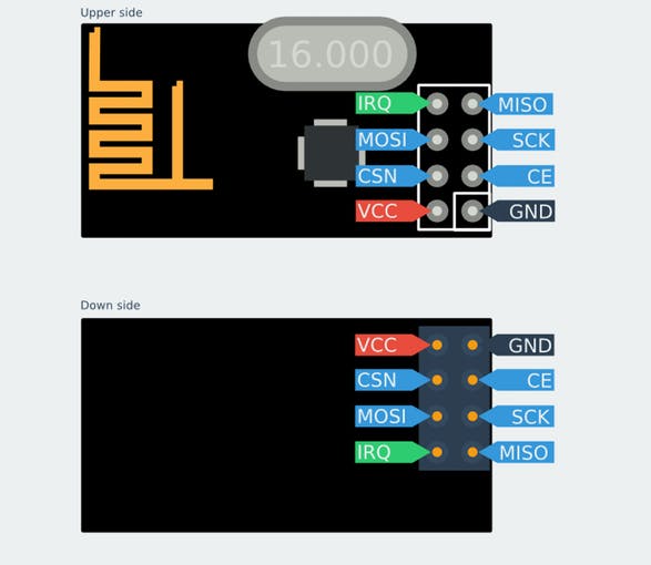
Pinout diagram for nRF24lL01
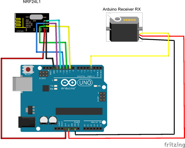
Reciver Circuit
Connect the nRF24L01 and servo moter to the arduino as per the above diagram.
Important note: Input voltage is of 1.9V~3.6V, do not exceed this voltage, otherwise it will fry your module.
- Arduino-------------nRF24L01
- Pin3-------------Servo signal pin
Now upload the receiver code given below to the first Arduino.
#include <SPI.h>
#include <nRF24L01.h>
#include <RF24.h>
#include <Servo.h>      // include the Servo library
Servo myServo;

int msg[1];
RF24 radio(9,10);//check your pin number on RF24 github check you have the right
//pin number for the arduino you're using. this pin is diffrent for diffrent arduino models.

const uint64_t pipe = 0xF0F0F0F0D2L;


void setup(void)
{
 myServo.attach(3);
  Serial.begin(9600);
  radio.begin();
  radio.openReadingPipe(1, pipe);
  radio.startListening();
  myServo.write(0);      // initial position of servo at angle 0

}

void loop(void)
{
  if(radio.available()){
    bool done = false;
    while (!done) {
      done = radio.read(msg, 1);
      Serial.println(msg[0]);
      if (msg[0] == 212) {
       myServo.write(180);
      }
      else {
            myServo.write(0);
      }
    }
  }
}
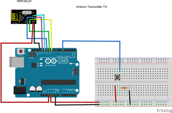
Transmitter Circuit
Connect the nRF24L01 and servo moter to the arduino as per the above diagram.
Important note: Input voltage is of 1.9V~3.6V, do not exceed this voltage, otherwise it will fry your module.
- Arduino-------------nRF24L01
Now upload the transmitter code given below to the second Arduino.
Now power both the Arduino boards and press the button and find that the servo rotates.
#include <SPI.h>
#include <RF24.h>
#include <nRF24L01.h>

int msg[1];
RF24 radio(9,10);//check your pin number on RF24 github check you have the right
//pin for the arduino you're using. this pin number is diffrent for diffrent arduino models.

const uint64_t pipe = 0xF0F0F0F0D2L;

int buttonPin1 = 5;
int buttonState1 = 0;

void setup(void)
{
  Serial.begin(9600);
  radio.begin();
  radio.openWritingPipe(pipe);
  pinMode(buttonPin1, INPUT);

}

void loop(void)
{
  buttonState1 = digitalRead(buttonPin1);


  if (buttonState1 == HIGH)
  {
    msg[0] = 212;
    radio.write(msg, 1);
  }

}
Thank you and hope that the tutorial helped you...