This Virtual Maze Solver/Path follower robot follows a path from a remote PC.
Introduction: Virtual Maze Solver Robot
Autonomous cars are now the most talked topics. Hobbyists try to make them using raspberry pi and computer vision technology. That's an approach. Another but easier way of making autonomous cars are line follower, path follower, maze solver robot. Such robots follow a certain color line drawn in certain environment's floor. We can make them using camera or IR sensor. What if I say that I don't want any line to be drawn on the floor, I want it to run on invisible line. This is what I did here actually. This Virtual Maze Solver/Path follower robot follows a path from a remote PC. So the robot doesn't have any sensors, it just gets coordinates from the PC - where another software robot tries to solve puzzle - and the hardware robot/car moves the way the software robot car moves. Watch the video for better understanding. Let me share now how I made this.
Step 1: Parts You'll Need
Hardware -
Software -
That's it. Now let's see how everything will work.
Step 2: Principle (How Everything Will Work)
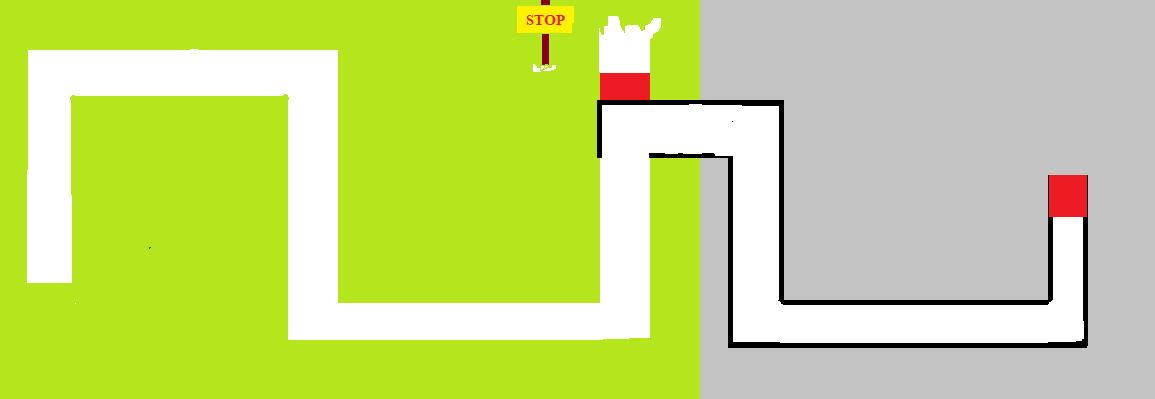
Simple, the robot will a Bluetooth controlled robot car. A python code will load a map/maze on computer and try to solve it. The hardware robot will get data from Python program using Bluetooth and move accordingly.
The python program will find path by comparing color value. Our map will consist white path. As long as there is a white pixel, the software car will go forward, so will the hardware robot.Now let's make it.
Step 3: Making Robot Chassis
I took some two PVC sheets and cut them according to my need. It's your choice how you want to make it. After cutting the boards/sheets I placed the motors, connected them with proper wires. Both motors of same side acts as one motor, so they are connected together. In image6 I used some female-to-female jumper wires to connect motor control pins to the PCB. After that I added two blue PVC pieces to decorate the body and connected the wheels.
Step 4: Circuit Diagram and PCB
I designed the circuit using EasyEDA. It's simple enough, I left all the analog pins except A4, A5 (those are for I2C communication) and added a SD card reader, bluetooth module and place for Arduino nano. The bluetooth module is separted by jumper (while uploading data, we need to disconnect that). We don't need resistors as Arduino will only receive data, it won't write.
After that I printed the PCB from PCBWay.com. I find their service very impressive. As they offer quality product in less amount of money, I prefer using their service for my PCB's. I went to pcb quick order and uploaded the gerber file. Everything was done automatically by the site. And after my PCB was inspected by their engineers, I paid and got them within 3 days to Bangladesh from China. The quality is amazing, solder mask, lines, glassy look amazes me as always.
- Left motors to D5, D6
- Right motors to D3, D4
The Bluetooth module is connected on the dedicated port but to be precise
- VCC to 5v
- Gnd to gnd
- tx to Arduino Rx
- Rx to Arduino Tx
What is your sending, is receiving on my end. So Arduino's receiving pin (Rx) is connected to Bluetooth modules sending pin (Tx).
After that powered the PCB from motor driver module. I always like to use a 7.4V power source for my robotics projects. Two lipo batteries will do the job. 3.7+3.7=7.4V, which is ideal for such projects.
So now our bluetooth robot is ready. Next step is programming it.
Step 5: Programming1: Arduino Code
Now it's time to upload the program to the robot. As bluetooth module is connected on hardware serial, I unplugged the jumper before uploading the code.
First I defined in which pin the motors are connected.
Then I declared the motor pins as output in setup() function.
Then I initialized serial communication to receive data from Bluetooth module.
It checks for byte data from serial port on which the bluetooth module is connected to.
- 'f' goes forward
- 'b' for backward
- l' for left and
- 'r' for right motion
For each motors there's two pins. If we need to run them to a direction we need to make a pin HIGH and other one LOW. If both of them are HIGH or LOW at the same time the motors won't spin.
With this combination we can make the robot to work.
Download the code from github .
Now upload the code using Arduino.ide and proceed to next step.
Step 6: Programmin2: Python Code
I suppose you have python installed on your computer. If you don't, go to python.org/downloads and install latest stable version of python. I use Python3.7.1 as I find it most stable. While downloading download executable installer, and double click it to install, then click on the box that says 'Add python to environment variable path', else you'll be in a disaster.
Anyway, let's now talk about the python program.
I needed two libraries for this program, pygame and pySerial. I installed them from my command prompt.
The two images you are seeing at the top are the maze and the software car. The python program reads them.
To send data from the PC to Arduino bluetooth I first connected the bluetooth module to my pc. Steps are -
- Turn on Bluetooth
- Go to control panel > device manager
- Search for new devices
- Add device (HC05) with password [default password is '0000' or '1234']
That's it. Then clicked on device properties to get the port no. of the HC05, in py PC it was in 'COM8'. So the python connects.
For the robot to check for surroundings first I found the center of the car and then checked it surrounding.
The rest of the code is checking surroundings and turning or moving the car. If it goes forward or any direction it sends that data to Arduino via serial port (byte data).
Now download the full code from github.
Step 7: Power Up and Let's Go
I powered the robot using two 18650 batteries. Then ran the Python program. How does it perform? You can see that in the video.
The best part of this robot is that you don't need to change robot's code time to time. You just need to change the python program accordingly. That's it.
This robot can be used in industries with some sensors on board to determine errors or in case it slips out of path and also to avoid obstacles. The sky is the limit, your brain is the master.