Learn how to measure torque force for build projects with Arduino.
In daily life, we're often presented with a range of statistics from product manufacturers that, at best, have a loose relationship with the experiences of actual users.
Smartphone manufacturers claim their batteries last far longer than they actually do. Tech companies advertise all their products as the most compact versions and car companies boast false fuel economy numbers.
Servo motor manufacturers are no different. They make various claims related to the amount of torque force their motors are capable of producing.
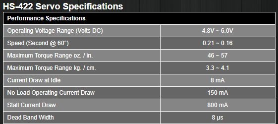
Specifications from the Hitec website for the HS-422 servo.
In this project, we'll be building a tool for measuring the torque range produced by standard-size servos.
In this way, it's easy to verify if a particular servo will produce the necessary torque force for a build.
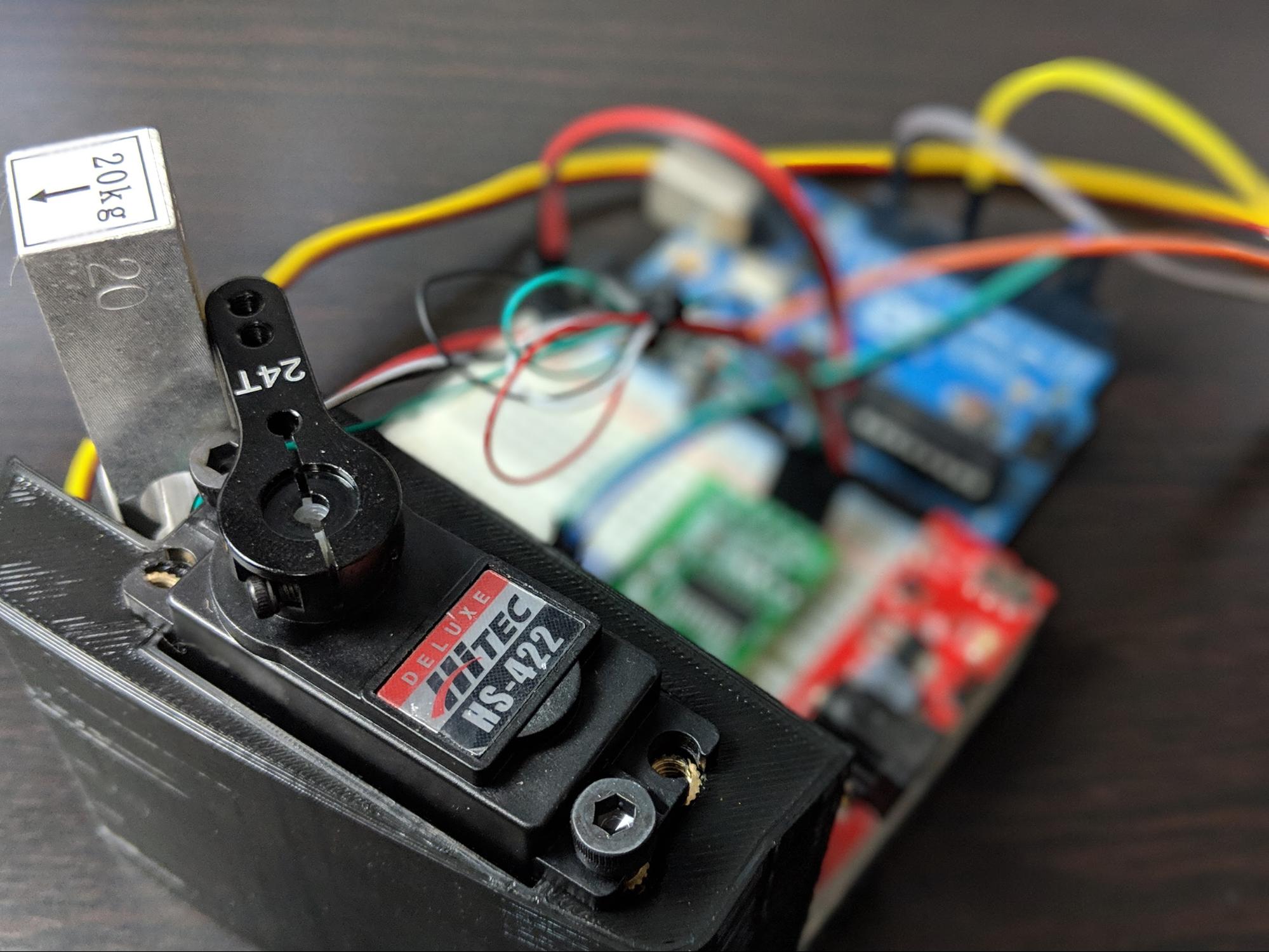
Using a load cell, an Arduino Uno, a 3D printed frame, and a few other parts, it's simply to load a servo into place and accurately measure the torque force it delivers.
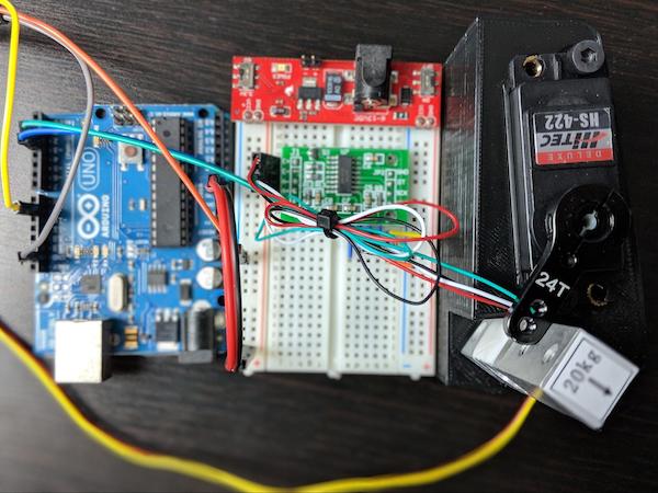
The required load cell, Arduino Uno, 3D printed frame and other components required for this project.
Overhead camera shot of the components required for this project.
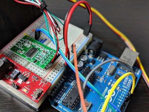
Close up camera shot of required components for this project.
Materials
- Arduino Uno
- 20kg load cell bar
- HX711 load cell amplifier breakout board
- Breadboard power supply
- Solderless breadboard
- 6-inch jumper wires
- 4x M4 heat-set inserts
- 2x M4 x 6mm screws
In addition to the above materials, you'll need a hobby-size servo for testing purposes.
How to Measure the Torque Force of a Motor Servo
Torque is computed by multiplying a force over distance. In this project, it will be slightly tricky to obtain the force exerted by the servo. To do so, a load cell will need to be used.
There are intricate details involved with the design and use of load cells, but for the purposes of this project, a load cell is a sensor that allows a computer to translate small voltage changes to a force.
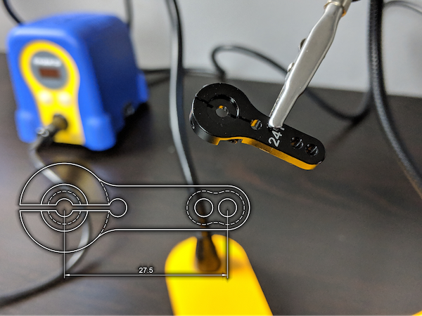
Using a load cell we'll be able to measure the exact distance between the axis of rotation for the servo and the arm on the servo horn.
Keep in mind that the servo will push against the load cell when it attempts to rotate.
Considering the force measurement from the load cell, as well as the rotation and servo arm distance, we'll be able to calculate the torque force delivered by it.
Building the Testing Tool
The mechanical design of the testing tool is simple and consists of two 3D printed parts and a couple fasteners.
You can find the design files for the 3D printed parts attached to this article.
There aren't any special printing parameters needed, so any rigid plastic for the parts will do.
In fact, since aesthetics aren't a priority for this project, you can use a high layer height to speed up the printing time.
Note: A Monoprice MP Select Mini with a layer height of 0.3mm to print the parts.
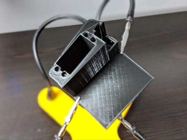
The project printed parts assembled together.
Assemble the Testing Tool
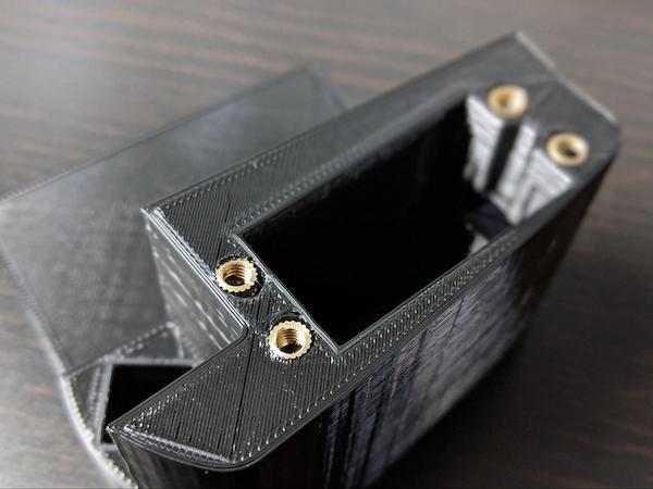
The first step in assembling the servo torque measuring tool is to install the heat-set inserts that allow the servos to be securely installed, and later uninstalled, without damaging the 3D printed frame.
To install the heat-set inserts, place each insert over one of the servo mounting holes.
Gently press the insert into the plastic using a soldering iron set to 250°F.
Don't push the insert too hard. Let the heat do the work for you and allow the insert to sink into the plastic.
When you remove the soldering iron, the molten plastic will solidify around the insert creating a very strong bond.
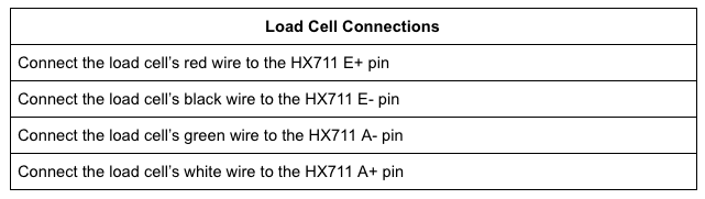
Next, install the load cell, which on one side will have a green arrow. Turn it up on that side with the arrow facing away from the servo, then insert the load cell into the square next to it.
The load cell should fit tightly into place, ensuring there isn't any flex in the mounting that would cause errors in the force measurements.
Finally, the large, flat area is used for the breadboard.
The breadboard has an adhesive backing. Just peel it off and stick the breadboard to the 3D printed frame.
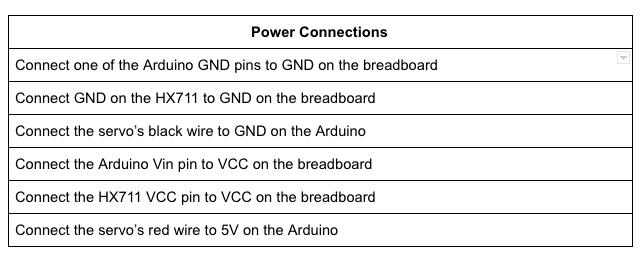
Populate the Breadboard
Once the mechanical design is complete, we can begin to work on the circuit.
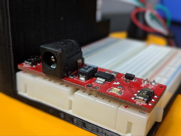
First, plug the breadboard power supply onto the end of the breadboard on the same side as the load cell. The power supply spans across the breadboard, so that the power delivery pins connect to the breadboard power rails.
There's a switch on the power supply that controls the output voltage.
For this project, we'll be using 5v. There's also an on/off switch on the power supply.
For now, turn the power off.
Power supply attached to the breadboard.
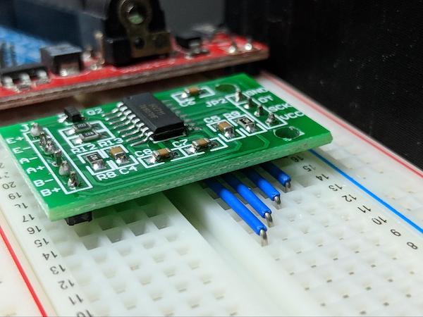
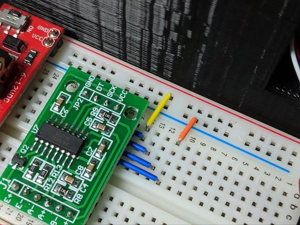
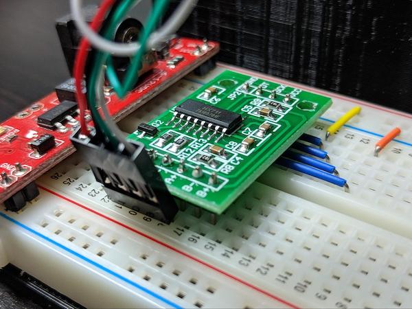
Now, a preparatory step should be taken before adding the HX711 to the breadboard.
The issue we have is that the HX711 board is almost as wide as the breadboard. If the HX711 is plugged into the breadboard, we won't be able to wire it.
Therefore, we'll actually place wires before the HX711.
There are four connections for the HX711 on the side closest to the servo. Use a small piece of wire to run across the breadboard about five spaces.
When we put the HX711 on top of the wires, we should still be able to plug other jumpers into the breadboard next to the HX711 and access it's pins.
To make this step a little clearer, check out the image below.
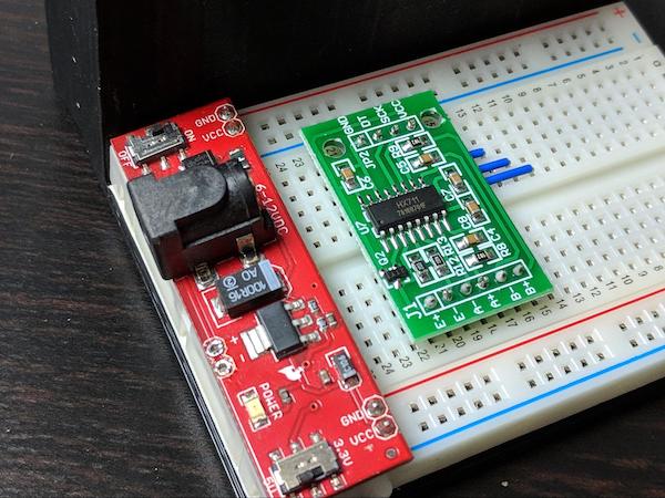
Once the wires are in place, plug the HX711 board in next to the power supply. Make sure the pins line up with the four wires.
The HX711 board plugged into the breadboard.
The HX711 board shown next to the power source.
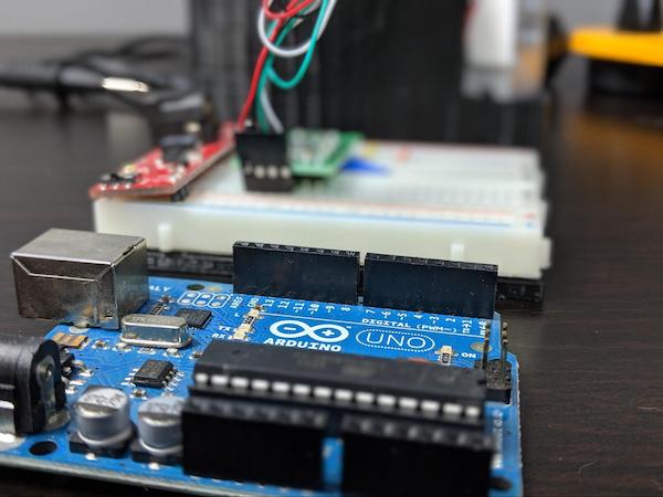
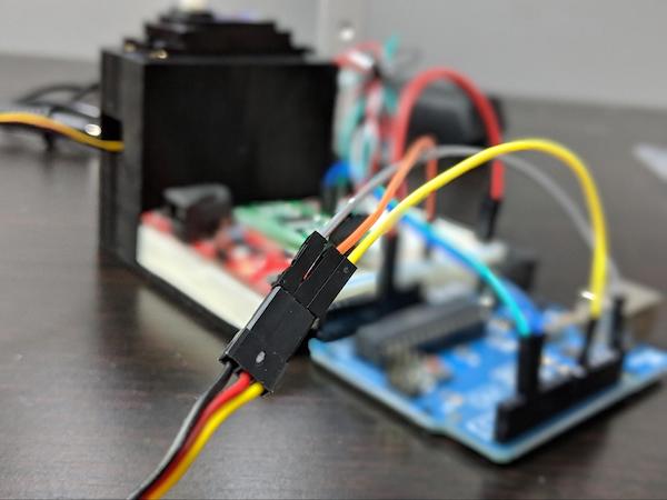
Finally, the Arduino Uno will sit alongside the torque measurement tool.
The torque measurement tool created in this project and the Arduino next to each other.
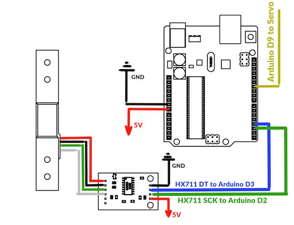
Diagram of circuitry for the project.
Programming the Arduino
When both the mechanical and the electrical assembly are complete, the final step is to upload firmware into the Arduino.
/*
Project: Measuring Servo Torque
Author: Toglefritz
This project involves a simple device used to measure the torque output of a hobby-scale servo. The device consists of a 3D printed frame that will hold a servo and a load cell. The servo rotates a horn into the load cell, producing a reading from the load cell. From the known distance between the servo's center of rotation and the load cell, the servo's torque can be calculated from the force on the load cell.
Complete documentation for the project can be found on Maker Pro.
*/
// Include libraries for interfacing with the HX711 and the servo
#include "HX711.h"
#include <Servo.h>
// Configuration
#define calibration_factor -7050.0 // This value is obtained using the HX711_Calibration sketch
int trialRuns = 5; // This defines the number of times to measure the servo's force on the
// load cell. These measurments will be averaged to come up with a single reading.
float armLength = 2.75; // This is the distance (in cm) between the servo's center of rotation and the load cell.
// This is based on the mechanical design of the test fixture.
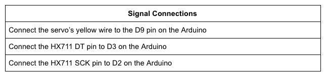
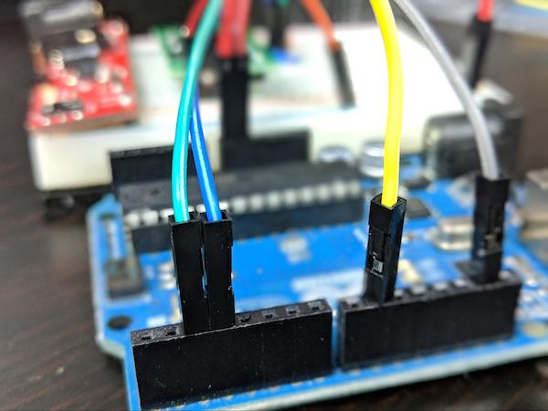
// Define connections between the HX711 and the Arduino
#define DT 3 // The HX711 DT pin connects to D3 on the Arduino
#define SCK 2 // The HX711 SCK pin connects to D2 on the Arduino
// Initialize the HX711
HX711 loadCell(DT, SCK);
// Create a servo object
Servo testServo;
void setup() {
// Begin Serial communication
Serial.begin(9600);
Serial.println(" - Torque Measurement Tool - "); // Print a heading
Serial.println();
// Set the pin used to control the servo
testServo.attach(9);
loadCell.set_scale(calibration_factor); // This value is obtained by using the HX711_Calibration sketch
loadCell.tare(); // Reset the scale to zero to compensate for any existing load
// To begin the test, the servo horn should be attached so that it is making contact with
// the load cell at an angle of 140 degrees on the servo
testServo.write(140); // Move the servo into the load cell
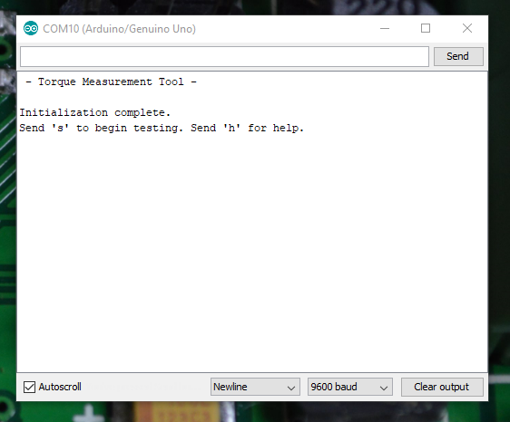
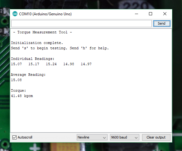
Serial.println("Initialization complete.");
Serial.println("Send 's' to begin testing. Send 'h' for help.");
Serial.println();
}
void loop() {
// If the user sends 's' over Serial, begin testing the torque
if(Serial.read() == 's' || Serial.read() == 'S') {
measureTorque();
}
// If the user sends 'i' over Serial, show some instructions
if(Serial.read() == 'h' || Serial.read() == 'h') {
Serial.println("Right now, the Arduino has moved the servo into its starting position.");
Serial.println("In the servo's current position, install the horn so that it is just touching the load cell.");
Serial.println("When you are ready, send 's' over Serial and the Arduino will begin testing the servo's torque.");
Serial.println("You will see the Arduino move the servo into the load cell five different times.");
Serial.println("Each time the servo hits the load cell, the Arduino will take a reading.");
Serial.println("Those readings will be averaged to calculate the torque delivered by the servo.");
Serial.println("Keep an eye on the Serial monitor to see the results.");
Serial.println();
Serial.println("Send 's' to begin testing.");
Serial.println();
}
}
void measureTorque() {
/*
To test the servo's torque, the Arduino will move the servo arm so that it presses on the load
cell. The resulting force will produce a reading from the load cell. The Arduino will take
five readings to compute an average force value. Because the distance between the servo's
center of rotation and the load cell is known from the frame design, the Arduino
can calculate the torque produced by the servo.
*/
Serial.println("Individual Readings: ");
float individualReadings[trialRuns]; // This array will store the load cell readings for the five tests
for(int i = 0; i < 5; i++) {
testServo.write(180); // Move the servo away from the load cell
delay(1000); // Wait for the servo to move
loadCell.tare(); // Reset the scale to zero to compensate for any existing load
testServo.write(130); // Move the servo into the load cell. A 130 degree angle is actually inside the load
// cell, so the servo will be pushing towards that position, exerting force on
// the load cell.
delay(1000); // Wait for the servo to move
individualReadings[i] = loadCell.get_units(); // Take a measurment from the load cell
Serial.print(individualReadings[i]); // Print the measurment over Serial
Serial.print(" ");
}
// Now that we have five individual readings, average them to get one average load reading
float readingsSum = 0; // Create a variable to store the sum of all readings
// Loop through the array and add together all the readings
for(int y = 0; y < trialRuns; y++) {
readingsSum = readingsSum + individualReadings[y];
}
float averageReading = readingsSum / trialRuns; // Divide by the numer of readings to get the average
Serial.println();
Serial.println();
Serial.println("Average Reading:"); // Print the average reading over Serial
Serial.println(averageReading);
// From the average reading, calculate the torque delivered by the servo
// using the formula T = F * r where T is the torque, F is the load cell
// reading (a force), and r is the radius of rotation (the distance between
// the servo and the load cell).
// The units for the torque will be kg*cm
float servoTorque = averageReading * armLength; // Calculate the torque
Serial.println();
Serial.println("Torque:"); // Print the torque
Serial.print(servoTorque);
Serial.println(" kgcm");
testServo.write(180); // Move the servo away from the load cell after the testing is complete
}
The testing procedure used by the Arduino is relatively simple.
The Arduino will drive the servo arm into the load cell. The resulting force on the load cell will produce a reading that the Arduino receives from the HX711.
The Arduino will cycle the servo five times, taking five individual readings from the load cell. Those five individual reads are then averaged to come up with a value for the force exerted on the load cell by the servo.
Because the distance between the servo's center of rotation and the load cell is calculated by the frame design. The Arduino can calculate the torque force produced by the servo from the average reading and the distance between the load cell and the servo.
Running the Test
After all the hard work assembling the servo torque tool and programming the Arduino, we can now finally measure the torque force produced by the servos. But first, we need to install the test servo into the measurement tool.
To install the servo, simply slide it into the housing.
The servo should be oriented for the motor shaft to be closest to the load cell.
The servo's wire will come out through a hole behind the load cell. It can be plugged into the Arduino from there.
To secure the servo into place, use at least two M4 x 6mm screws.
The system can be powered entirely from your computer's USB port.
If you only use the USB power, the servo will run off 5V. Since servos are typically powered by a range of voltages, you can also use the power bar on the breadboard.
This will allow you to provide the servo with a higher voltage than the 5V over USB connection.
Once you have the system powered, open up a serial monitor. You will be prompted to send 's' over serial when you are ready to begin the test.
The Arduino should start to move the servo arm away from the load cell at this point, once it does run it back into the load cell.
Since the the servo is trying to move to a position inside the load cell, it will exert a force on it.
The Arduino will measure this force, convert it into torque, and send the results to the serial monitor.