Play Tic-Tac-Toe (also known as Xs and Os) using handwritten digits recognized with the help of TinyML techniques
Play Tic-Tac-Toe (also known as Xs and Os) using handwritten digits recognized with the help of TinyML techniques.
Introduction
I am pretty sure that you’ve come across a popular Tic-Tac-Toe game that can be played by anyone from all age ranges. If not, I will provide a brief explanation. This strategy game, also known as noughts and crosses (or Xs and Os), is more common among kids to help them develop their planning, problem-solving and cognitive skills. It can be played as a classic paper-and-pencil game or even as a computer game. The players have a three-by-three grid and take turns in placing Xs and Os. The player who places three of his marks in a vertical, horizontal, or diagonal row wins the game.
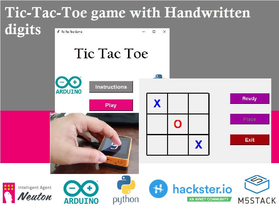
Recently, I’ve been really interested in developing smart interfaces, and I came up with an idea to implement the Xs and Os game on the M5Stack Core using TinyML techniques. In this project, I’ll show the whole implementation pipeline. Here’s a teaser of what we’ll get as an outcome:
Overview - Game and Software
For my experiment, I created the game using Tkinter and Python. This is a two-player game so you will need someone else to play with you!
Another important aspect is how to draw the Xs and Os. This is where our M5Stack Core 2 ESP32 IoT Development Kit (I will call it M5Stack from here) and Neuton TinyML come into play. By the way, though Neuton is not an open-source tool, all functions are free and its models can run on almost any MCU.
Then I focused on preparing a proper dataset. I was inspired to apply this idea after taking a look at the MNIST dataset. I will explain why as you read further :)
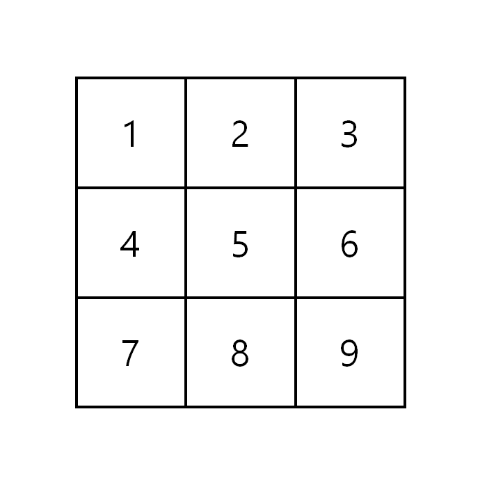
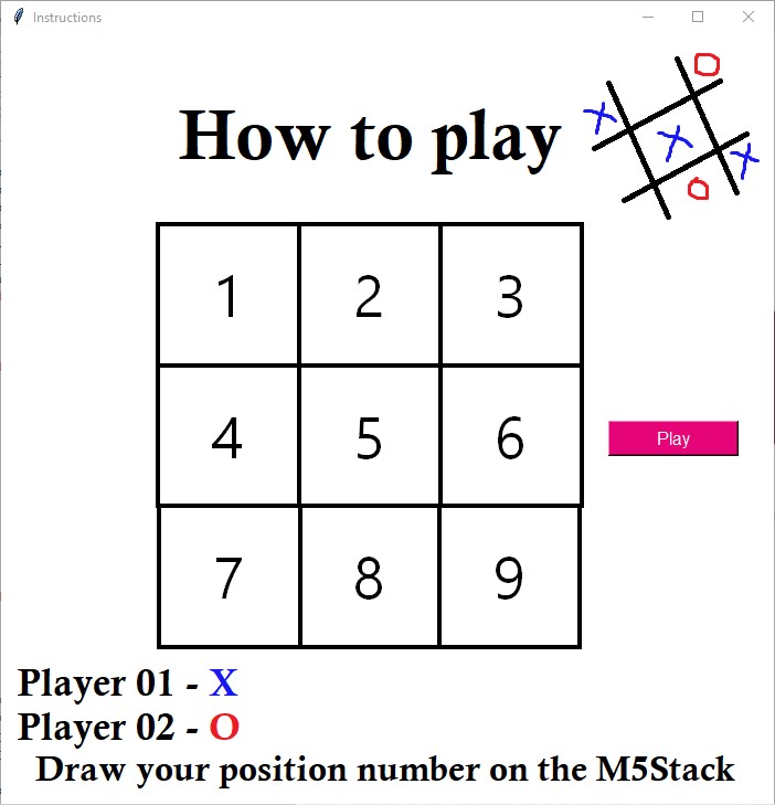
I drew the position number on the M5Stack and the respective mark was to be placed on the specified position in the 3x3 grid. The handwritten digit would be predicted by the Neuton TinyML model and the model's output would be passed on to the Python program.
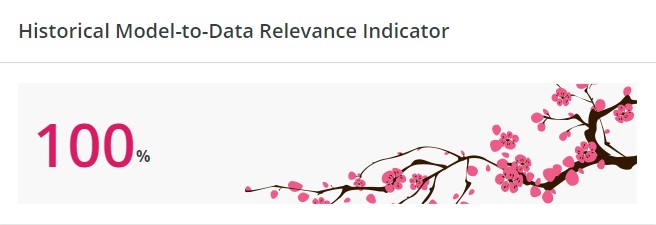
MNIST Dataset & Its relevance to the Project
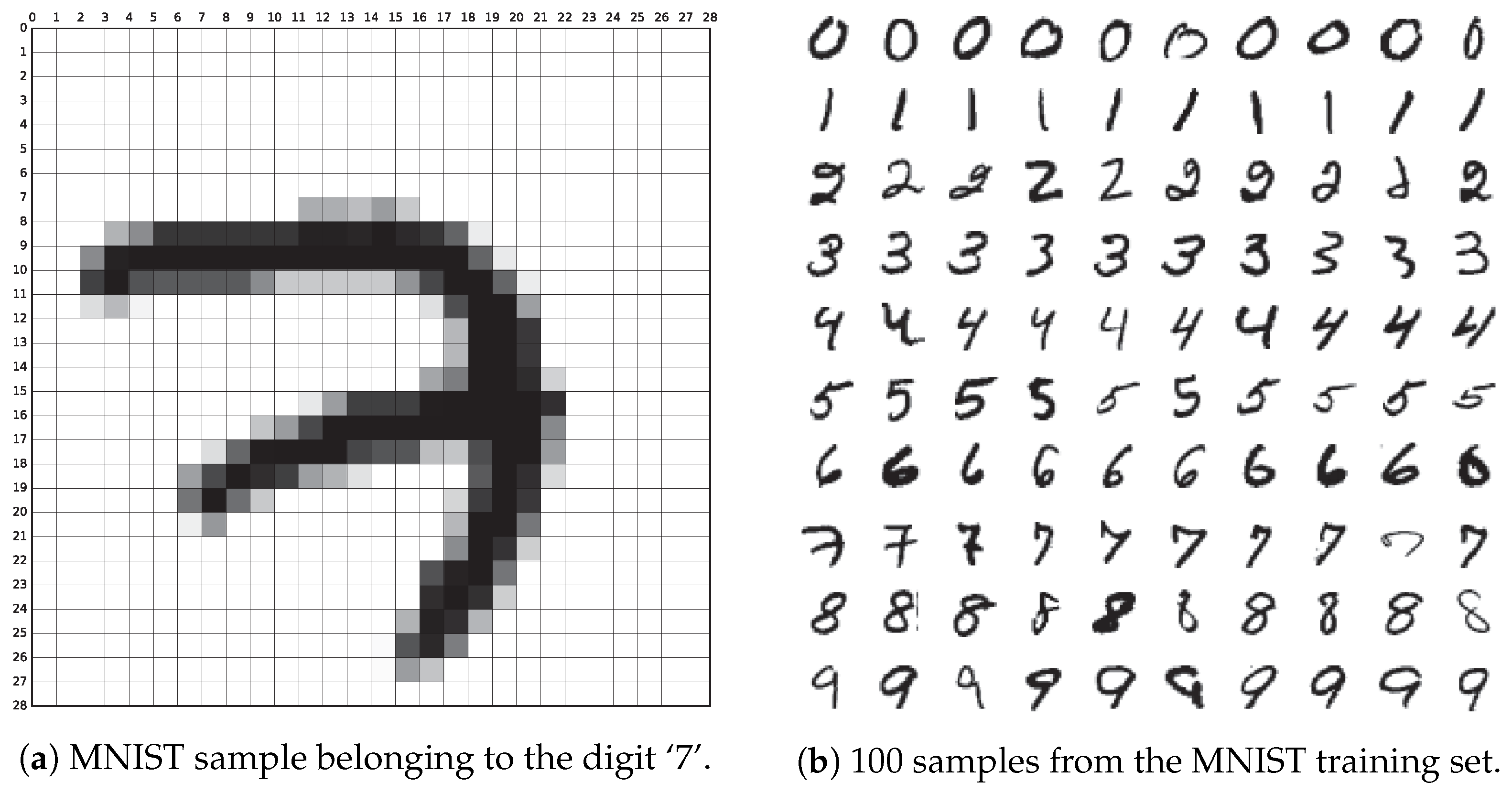
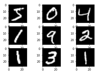
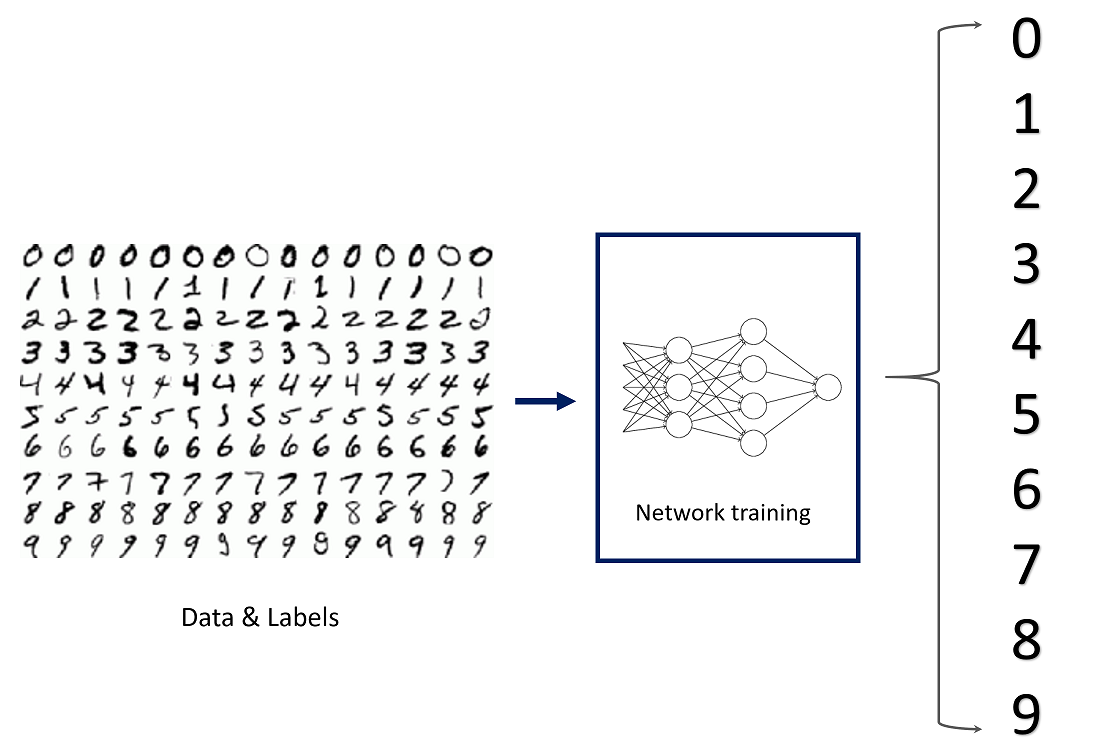
The MNIST (Modified National Institute of Standards and Technology) dataset is the "hello world" dataset of computer vision, sourced from the MNIST database which is a large collection of handwritten digits.
Each sample is a 28x28 grayscale image of a hand-drawn digit between 0 and 9. There are 784 pixels in total and each pixel value indicates the lightness/darkness of the respective pixel. A higher pixel value means the pixel is dark and if it's low – the pixel is light. The pixel value has a range of 0-255 (inclusive).
Neuton already has pre-trained datasets that are ready for deployment and the MNIST dataset is one of them. The training dataset contains 42, 000 samples while the test dataset contains 28, 000 samples. The target variable of the training dataset is the 'label' variable which contains the digit that should be recognized and the feature variables are the pixel locations which contain the pixel values of the respective pixels.
The pixel location of a pixel is calculated using the following formula:
x = i * 28 + j
x is the pixel location. I and j are integers between 0 and 27 (inclusive). I denotes the pixel's row while j denotes the pixel's column and the indexing is by zero.
I decided to create my own dataset based on this idea.
Data Collection: Preparing the Training and Test datasets
I used my M5Stack to collect the data and prepare the training and test datasets. I decided to assign 75% of the data as the training dataset and the remaining 25% as the test dataset.
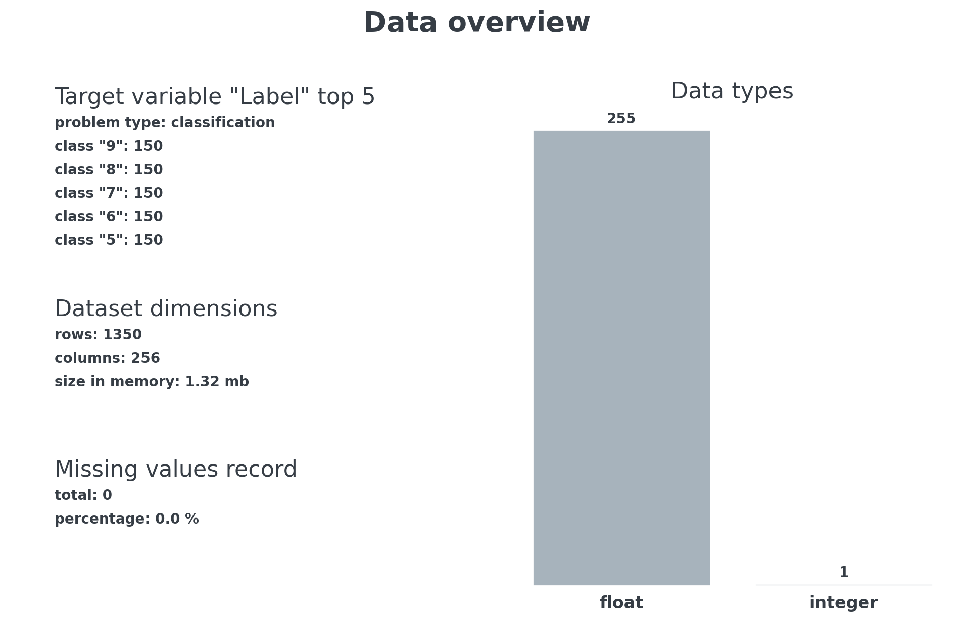
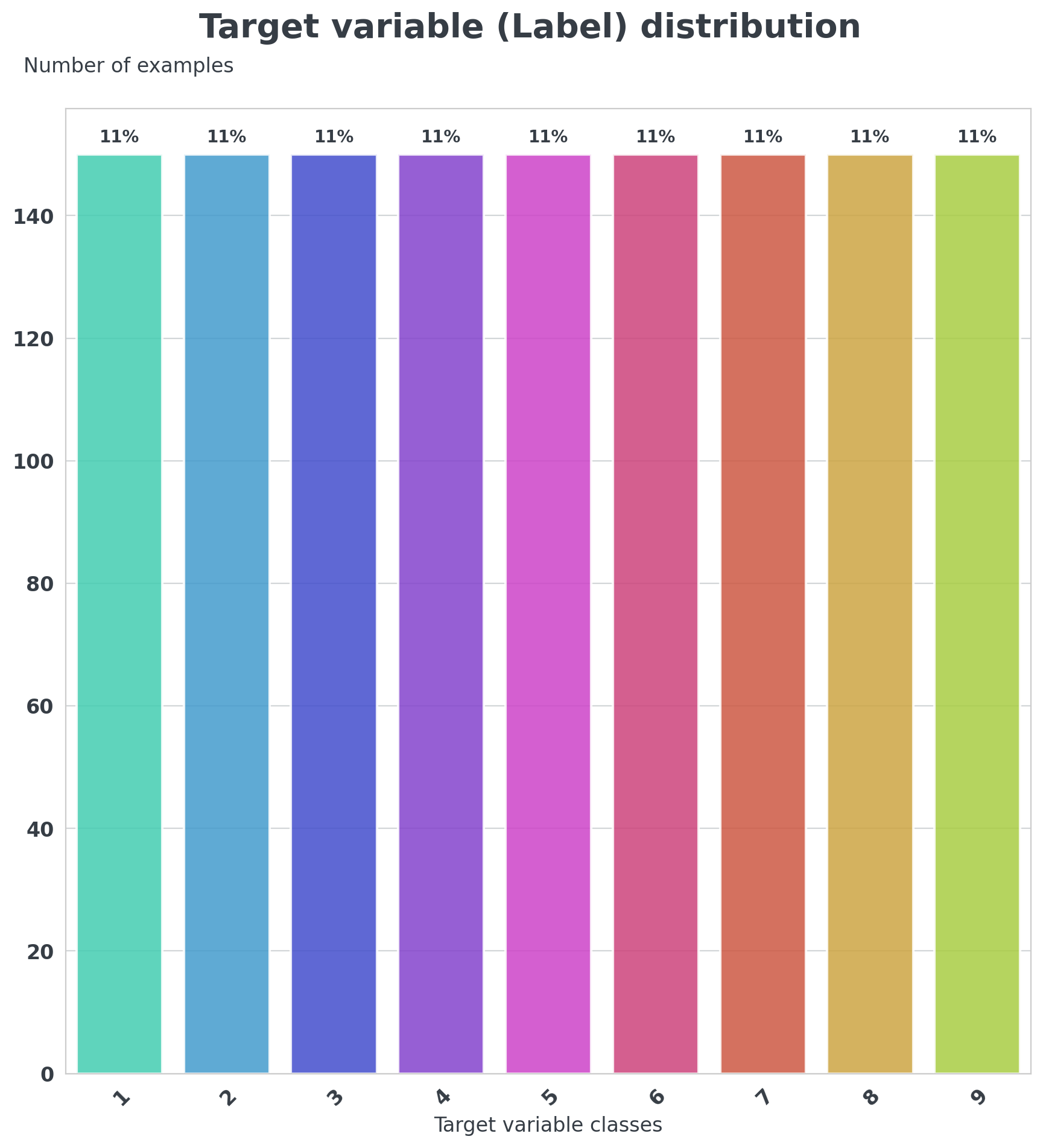
The target variable of my training dataset will be the 'Label' variable and it will contain the position number. The position number ranges from 1 to 9, inclusive. I collected 200 samples for each digit, 150 of which belonged to the training dataset and 50 of which belonged to the test dataset. There will be 255 feature variables that contain the pixel values of the respective pixels. The MNIST training dataset contained 784 feature variables but I decided to narrow it down to 255 in my dataset as I won't be drawing the digit all over the screen. I verified the approximate number of pixels that had significant pixel values as I drew my digits and decided to use 255 feature variables.
The screen resolution of the M5Stack is 320 x 240 pixels. To calculate the pixel location, I used the following formula:
x = i * 320 + j
The factor by which you multiply the pixel's row number is basically the width of your touchscreen. To store the pixel values, I tried using the list method. I declared a list and then tried to append the pixel values within a for loop (with 255 iterations) but it was not successful as I kept getting an error saying that the pixel location did not have an appropriate data type. To save time, I decided to use the buffer method instead where I allocated memory to store pixel values.
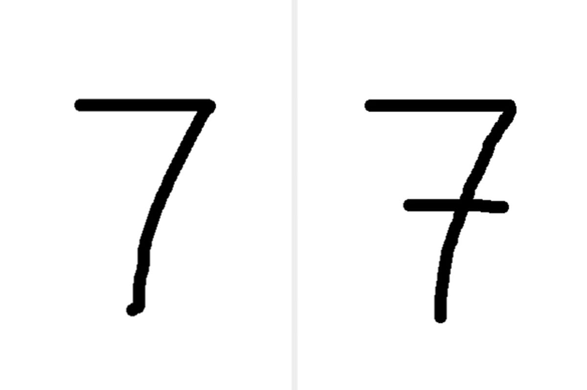
Each person will have a different way to write a number, so I made sure to draw out each number in all possible ways and collect sufficient samples for each way.
Neuton TinyML requires the datasets in a CSV format so I prepared my training and test datasets as CSV files. Your dataset, both training, and test, will have to meet some other requirements as well, but don't worry, you can always view them in the Support Library on the platform.
The code for data collection is available in the Code section below.
The next step is model training.
Training the Model
Visit the Neuton TinyML's web page (neuton.ai) and click on ‘Get Started’. Click on the ‘Start for Free’ button and you will be redirected to the welcome page where you can sign in using your Google account and get started. Set up your CGP account and you will receive free credits to upload your own data and train your models. Subscribe to Neuton's Zero Gravity Plan and you are good to go!
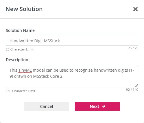
Click on 'Add New Solution' and you will see something like this:
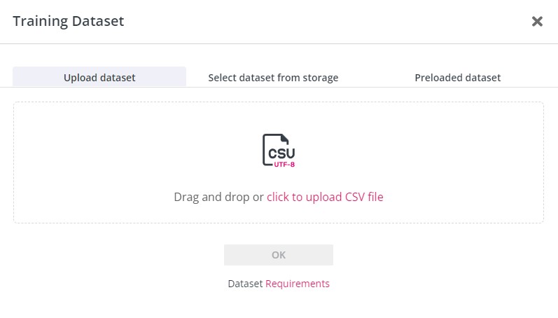
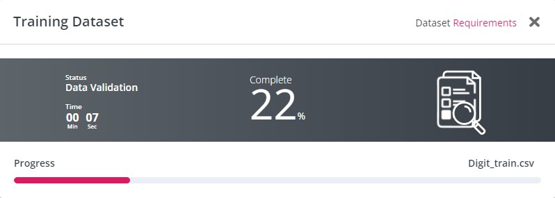
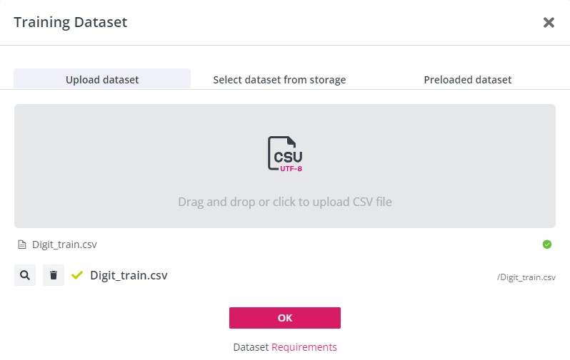
Once you are done, click ‘Next’ and you will be required to upload your training dataset. The dataset will be validated and if it meets all requirements, it will show a green tick and allow you to continue. You should not have duplicate rows or any missing values.
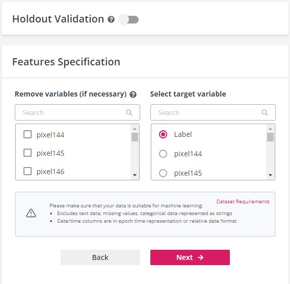
Click ‘OK’ and proceed to the next step. Choose your target variable which is the 'Label' variable and if you want to eliminate any other variables, you can also do that.
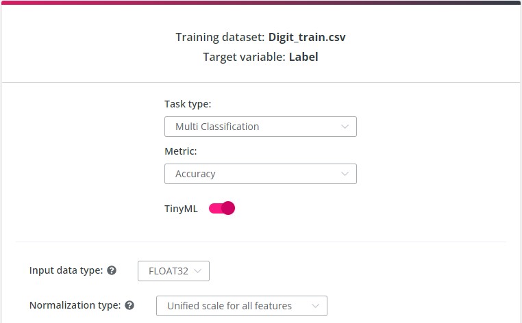
The next step will require you to specify the task type, the metric, and TinyML model settings. The platform can identify the target metric and task type itself but I will explain why I used the Classification task type.
This model should be able to classify the given input as a digit within 1-9 and this is supervised machine learning as we are training the model with the target and feature variables.
This is classification since we are not predicting a continuous dependent variable using independent variables like predicting the yearly income using the number of hours worked per week. There are two types of classification - binary and multi. Binary classification will classify the input into one of the two classes. But in this project, we will be classifying the input into one of the nine classes so the task type is Multi Classification in this case.
The target metric is Accuracy and you will eventually know why the platform chose it after your model's training is complete. The target metric calculates the error rate of the model predictions on the validation dataset and represents the model quality.
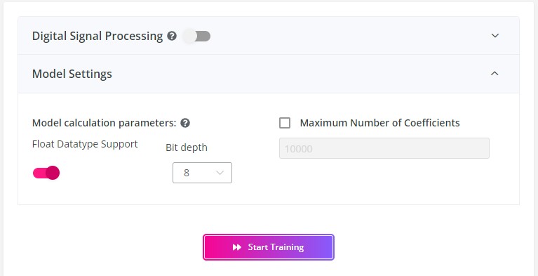
If you want to create tiny models for microcontrollers, enable the TinyML mode using the slider and set the model settings.
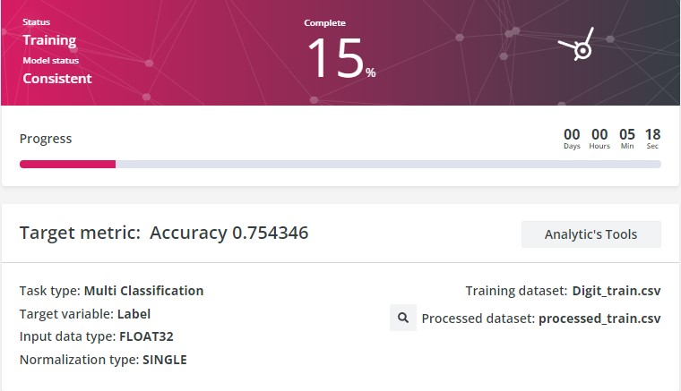
The input data type is FLOAT32 and the normalization type is 'Unified scale for all features'. You will need to choose this normalization type if the data from your feature variables are within the same range and doing this will also reduce the time required for training. Enable float datatype support and select 8 bits as the bit depth for calculations. Once you are done, click 'Start training' and the training process will start.
You can view the quality of your model, its accuracy, and other analytics once your training is complete.
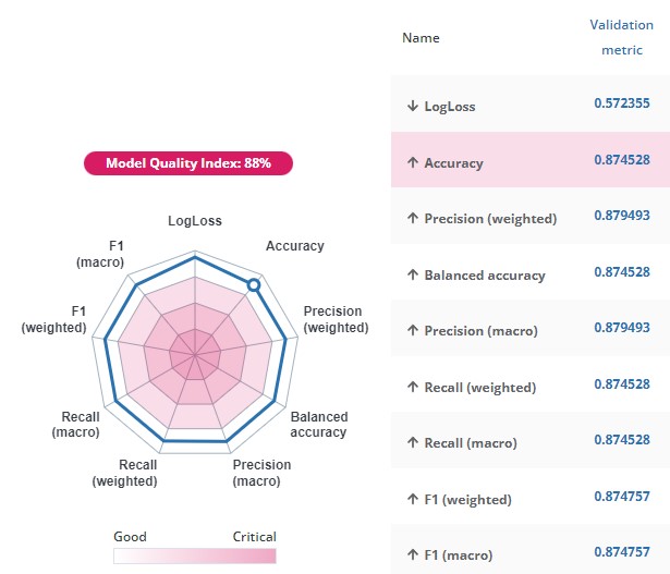
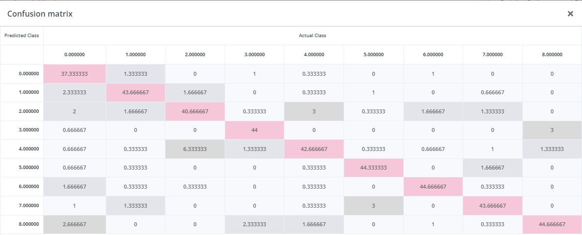
Training results
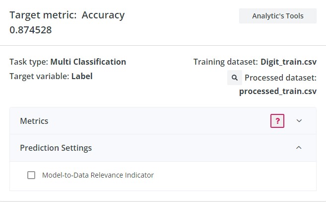
My model had an accuracy of 87.5% and a model quality index of 88%. I am satisfied with the results!
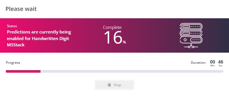
Prediction
I enabled prediction to see how well my model performed. For this, I used my test dataset.
The results were better than expected and I felt quite confident about my TinyML model. I downloaded the C library and got ready to deploy it on my M5Stack.
Embedding the Neuton Model on M5Stack
Create an Arduino sketch file to deploy your model. After downloading the C library, extract the zipped folder and copy the contents into the folder with your sketch file. Read the README text file within the downloaded content to learn how to embed your model.
According to the README file, the two main functions are:
- neuton_model_set_inputs - to set input values
- neuton_model_run_inference - to make predictions
You will need to make an array with model inputs. In my case, I have used a buffer as my input data type was not suitable for an array. Please make sure that the input count and order are the same as in the training dataset. Pass this to neuton_model_set_inputs function. The function will return 0 when the buffer is full and this indicates that the model is ready for prediction.
You should call neuton_model_run_inference function with two arguments when your buffer is ready. These two arguments are:
- pointer to index of predicted class
- pointer to neural net outputs
As you can see in the code below, 0 is returned by neuton_model_run_inference function when the prediction is successful.
if (neuton_model_set_inputs(inputs) == 0)
{
    uint16_t index;
    float* outputs;

    if (neuton_model_run_inference(&index, &outputs) == 0)
    {
        // code for handling prediction result
    }
}
After a successful prediction, classification takes place and the inference results are mapped on your classes (1-9). Note that the inference results are encoded (0..n). Use dictionaries binary_target_dict_csv.csv / multi_target_dict_csv.csv for the mapping process.
I have uploaded the complete source code in the Code section for your convenience.
Python application
Now we have a successful model that can recognize handwritten digits. Right now, it is displaying the classification output on the Serial Monitor. The next step is to develop the Tic-Tac-Toe game and help our M5Stack "communicate" with the Python application.
You will be needing the following libraries for this project:
- Tkinter - standard GUI library for Python
- Serial - Allows access to the serial port
- Time - Used in this project to set delay periods
Five python files will be created and let me break this down for you:
- Splash - This file will be the homepage of the game.
- Game - This will be the file that contains the codes for the game.
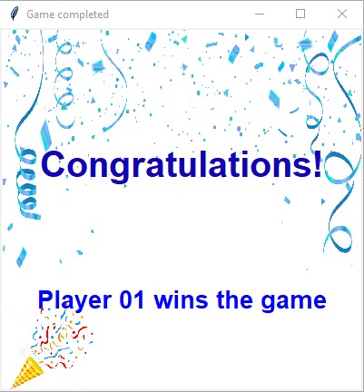
- P1 - Displayed when player 01 wins the game
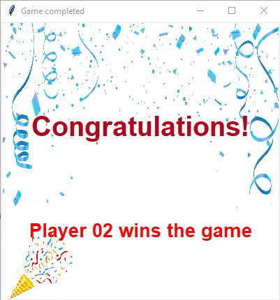
- P2 - Displayed when player 02 wins the game
- Draw - Displayed when the game is tied
Tkinter only supports a maximum of two Python file imports so I decided to include the code of the instructions page within the splash file itself.
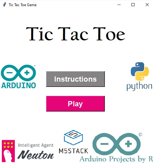
Splash.py
In this section, I will be explaining how I created the homepage of this game. You will need the font module to format the button text and this is completely optional. I set the background image as a label. To use an image in Tkinter, you will need to use the PhotoImage function. Make sure that the image is in.png format. If you want to use a different image format, you will need the PIL library and as it is not a standard library, you should install it.
#Importing the libraries required for the homepage
from tkinter import *
import tkinter.font as font

#Creating a tkinter window
start = Tk()
start.geometry('500x500')
start.title('Tic Tac Toe Game')

#Applying a background image to your homepage
bg=PhotoImage(file= r"location of your background image")
label1 = Label( start, image = bg, border =0)
label1.place(x = 0,y = 0)

#Specifying the font
head_font = font.Font(family="Helvetica", size = 18, weight="bold")

...
start.mainloop()
I have used the button widget to create the Instructions and Play buttons. I also set the foreground and background colors using hex codes. The command is a function that will be called once you press the button. In this case, the play button should destroy the homepage and import the Python file which contains the codes for the game.
Play_Button = Button(master=start, text="Play", command=play_game, font = head_font,  relief = 'raised', fg="white", bg="#e60579", width=12)
Play_Button.place(x=150,y=280)
The instructions page is programmed within a function so there won't be any requirement to import a Python file for this case. You only have to create the button widget to play the game and the others are part of the background image.
Game.py
In this file, you will need to import the Tkinter, serial, and time libraries. You will also need to import the font and messagebox modules from Tkinter. As I already mentioned, the font module is optional. The messagebox module is used to display a question-type message.
Create a Tkinter interface and set up your fonts. You will need to create three empty lists which are positions, cross, and nought.
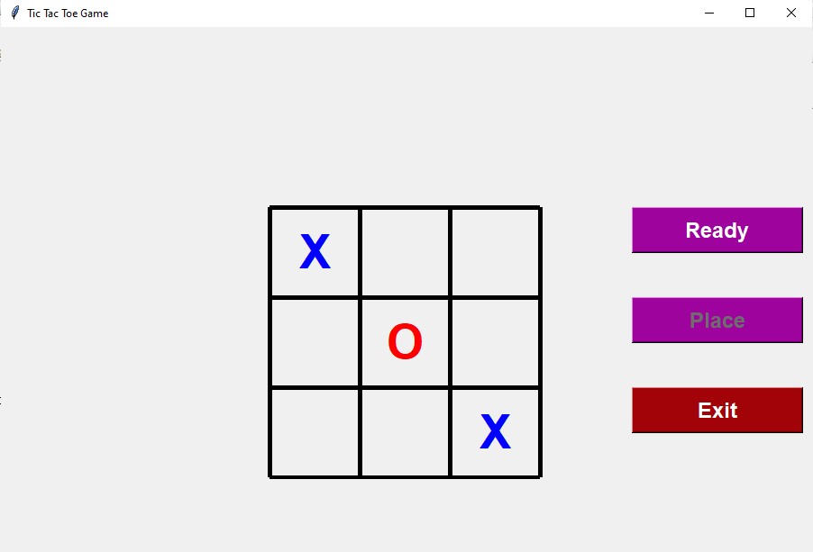
Use the canvas widget to draw out the 3x3 grid as shown in the pictures above.
canvas = Canvas("tkinter window", width=500, height = 500)
canvas.pack()

#Draw a line
canvas.create_line(x1, y1, x2, y2, fill="your line colour", width=5)
#You will need 4 horizontal lines and 4 vertical lines that are equally spaced out
You have three buttons here so you will need to create three-button widgets and, as mentioned in the previous section, you will need three functions for these buttons to implement when they are pressed.
I will first explain the functions because the functions should be defined before creating the buttons.
You will first define the function that will be called when the 'Ready' button is pressed. Your M5Stack will communicate with the Python application via a serial communication port. In the Arduino code, I programmed my M5Stack to print the model prediction output as a line in the Serial monitor. In this Python file, you will have the read the serial input. time.sleep(2) sets a delay period of 2 seconds.
ArduinoSerial=serial.Serial("your serial communication port","Baud rate")
time.sleep(2)
serial_input = str((ArduinoSerial.readline()).decode('utf-8'))
You can check the datatype of your Arduino Serial input using the type() function and it will show that the input is encoded in UTF-8 format. I will need the serial_input as a string so I have decoded it and converted it to a string.
Now, you will need to define the function that will be called when the 'Place' button is pressed. First, you have to check if a specific digit is in the serial_input variable to place the mark in the respective position. Then, you have to check if the digit is in the positions list to verify that the position is not occupied. If the position is already occupied, you have to display an error message and if it is not, you have to proceed to check if the position list's length is even or not - xo_decision( ). Nought and cross will be determined after calculating the position list's length at each turn. Player 1 will get the cross mark while player 2 will get the nought mark.
Initially, the position list will be empty so when the length is calculated, it will return 0. 0 is even, so I have programmed this application to assign a cross as the mark if the position length is even. If it's not, the mark is a nought. Place your mark at the respective coordinates (depends on your grid coordinates). The position number should be appended to the position list and the label should be configured to show no text at all. If there's an error message, then doing this will remove the error message from the Tkinter window.
if 'one' in serial_input:
        if '1' in positions:
            Label1.configure(text="Error: Position occupied")
        else:
            xo_decision()
            canvas.create_text(150,250,text=mark, fill=colour, font =("Helvetica 40 bold"))
            positions.append('1')
            Label1.configure(text=" ")
Repeat this step for all the nine digits.
To check if the length is even or not, you will need to use the modulo operator which returns the remainder of the integer division. You would have noticed that the cross is blue whereas the nought is red. We will be assigning the colors based on the result of this conditional programming.
length = len(positions)
if (length%2==0):
    mark = "X"
    colour = "blue"
    cross.append("digit")
else:
    mark = "O"
    colour = "red"
    nought.append("digit")
The 'Ready' button is pressed when the user is ready to draw the digit and as soon as the input is received, the 'Place' button should be enabled. You may now know how to create a button widget after reading it in the previous section but this time, you will have to access another property to enable/ disable the button state. As soon as the 'Place' button is enabled, the 'Ready' button should be disabled. You can change the state of the buttons using.configure( ). You should include this in the buttons' functions after creating the button widgets.
Place_Button = Button(master=ws, text = "Place", command = place, state="disabled",   font = labelFont, relief='raised', fg = "white", bg ="#9e039e",width = 12)
Place_Button.place(x=700, y=300)
When the 'Place' button is enabled, you can click on it to place your mark. Once your mark is placed, the 'Ready' button should be enabled and the 'Place' button should be disabled again.
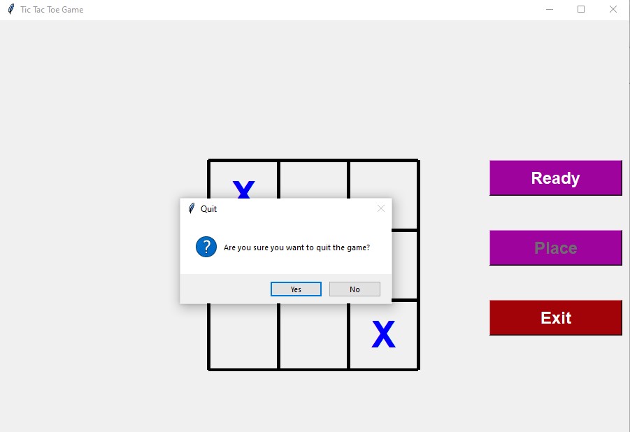
As visible in the second picture, the 'Exit' button's function should display a question-type message asking the user if they are sure about quitting the game when the 'Exit' button is pressed. If the user clicks the 'Yes' button, then the game window should disappear.
P1.py, P2.py and Draw.py
The three files will have similar codes. You can create a Tkinter window and apply a background image showing the result.
Final Look
This is a video showing the final outcome of this project.
Conclusion
TinyML models have a range of applications and this project is one of them. I feel satisfied with the resulting model as it works greatly on the device and I had a nice experience while recreating this popular paper-and-pencil game :) I hope you liked my tutorial and found it helpful. I'm always open to suggestions so please feel free to share your feedback below.
Code
Touch Test - This is an example sketch file from M5GFX library that allows you to test your device and see how the touch points are drawn on the screen. Try using this example to understand how the device works and to verify that your device is working properly.
//This is an example sketch file from M5GFX library that allows you to test your device and see how the touch points are drawn on the screen. Try using this example to understand how the device works and to verify that your device is working properly.
#include <M5GFX.h>

M5GFX display;

void setup(void)
{
  display.init();
  display.setFont(&fonts::Font4);

  if (!display.touch())
  {
    display.setTextDatum(textdatum_t::middle_center);
    display.drawString("Touch not found.", display.width() / 2, display.height() / 2);
  }

  display.setEpdMode(epd_mode_t::epd_fastest);
  display.startWrite();
}

void loop(void)
{
  static bool drawed = false;
  lgfx::touch_point_t tp[3];

  int nums = display.getTouchRaw(tp, 3);
  if (nums)
  {
    for (int i = 0; i < nums; ++i)
    {
      display.setCursor(16, 16 + i * 24);
      display.printf("Raw X:%03d  Y:%03d", tp[i].x, tp[i].y);
    }

    display.convertRawXY(tp, nums);

    for (int i = 0; i < nums; ++i)
    {
      display.setCursor(16, 128 + i * 24);
      display.printf("Convert X:%03d  Y:%03d", tp[i].x, tp[i].y);
    }
    display.display();

    display.setColor(display.isEPD() ? TFT_BLACK : TFT_WHITE);
    for (int i = 0; i < nums; ++i)
    {
      int s = tp[i].size + 3;
      switch (tp[i].id)
      {
      case 0:
        display.fillCircle(tp[i].x, tp[i].y, s);
        break;
      case 1:
        display.drawLine(tp[i].x-s, tp[i].y-s, tp[i].x+s, tp[i].y+s);
        display.drawLine(tp[i].x-s, tp[i].y+s, tp[i].x+s, tp[i].y-s);
        break;
      default:
        display.fillTriangle(tp[i].x-s, tp[i].y +s, tp[i].x+s, tp[i].y+s, tp[i].x, tp[i].y-s);
        break;
      }
      display.display();
    }
    drawed = true;
  }
  else if (drawed)
  {
    drawed = false;
    display.waitDisplay();
    display.clear();
    display.display();
  }
  vTaskDelay(1);
}
Data Collection - Use this to collect data and prepare your dataset
#include <M5GFX.h>

M5GFX display;
int val;
int iteration;
const int Buffer_Size = 450;
int* Buffer = (int*) calloc(Buffer_Size, sizeof(int));   // allocate memory for pixel buffer with 0s

void setup() {
  // put your setup code here, to run once:
  Serial.begin(115200);
  display.init();
  display.setFont(&fonts::Font4);

  if (!display.touch())
  {
    display.setTextDatum(textdatum_t::middle_center);
    display.drawString("Touch not found.", display.width() / 2, display.height() / 2);
  }

  display.setEpdMode(epd_mode_t::epd_fastest);
  display.startWrite();
  Serial.print("Label");
  for (int i=0;i<450;i++){
    Serial.print(",");
    Serial.print("pixel"+String(i));
  }
  Serial.println();
  Serial.print("Y");
}

void loop() {
  // put your main code here, to run repeatedly:
  static bool drawed = false;
  lgfx::touch_point_t tp[3];

  int nums = display.getTouchRaw(tp, 3);

  if(nums)
  {
    display.convertRawXY(tp, nums);
    for (int i = 0; i < nums; ++i){
      // ensure no duplication of touch points
      if((tp[i].y * 320 + tp[i].x) != val && iteration < 450){
        Buffer[iteration] = (tp[i].y * 320) + tp[i].x;
        val = Buffer[iteration];
        iteration++;
      }
     }
     display.display();
     display.setColor(display.isEPD() ? TFT_BLACK : TFT_WHITE);
     for (int i = 0; i < nums; ++i)
     {
      int s = tp[i].size + 4;
      switch (tp[i].id)
      {
      case 0:
        display.fillCircle(tp[i].x, tp[i].y, s);
        break;
      case 1:
        display.drawLine(tp[i].x-s, tp[i].y-s, tp[i].x+s, tp[i].y+s);
        display.drawLine(tp[i].x-s, tp[i].y+s, tp[i].x+s, tp[i].y-s);
        break;
      default:
        display.fillTriangle(tp[i].x-s, tp[i].y +s, tp[i].x+s, tp[i].y+s, tp[i].x, tp[i].y-s);
        break;
      }
      display.display();
    }
    drawed = true;
   }

    // clear the screen and go to default state once the sample is drawn
   else if (drawed)
   {
    for(int i = 0; i < 450; i++){
      Serial.print(",");
      Serial.print(Buffer[i]);

    }
    Serial.println();
    Serial.print("Y");

    drawed = false;
    display.waitDisplay();
    display.clear();
    display.display();
    val=iteration=0;
    free(Buffer); // free the memory
    Buffer= (int*) calloc(Buffer_Size, sizeof(int));     // reallocate memory for pixel buffer with 0s
   }
   vTaskDelay(1);
}