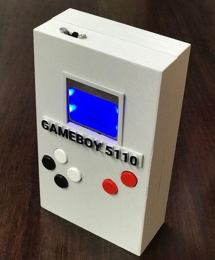
As a game enthusiast, DIY a retro game console by taking advantage of an old Nokia 5110 screen, which instantly brings you back to your childhood. Sounds great? Let’s have a look here.
Introduction
During the COVID-19 crisis, how to spend a lot of quarantine time at home? In addition to improving cooking skills and doing sports, game lovers can also make their own unique GameBoy game console! The blue backlit LCD screen of the Nokia 5110 is used here (which makes it more retro style) and the 3D printed GameBoy shape shell. The project is based on Arduion Nano, you can also use your favorite hardware.
Characteristic
1. With six programmable buttons, it is convenient to upload your favorite games.
2. The four keys on the left are arrow keys, and the upper button on the right is the reset button. You can change the controls in the Arduino file.
3. The sound part adopts piezoelectric buzzer.
Specific Material (The Rest)
Nokia 5110 LED LCD screen × 1
Piezo buzzer × 1
Button B3F Omron 12mm (multiple colors) × 6
Prototype board × 1
Wire × several
DuPont wire in in female × 1
PLA printing material × 1
Nut × several
2mm bolt × several
Soldering iron × 1
Tin and flux × 1
Glue gun × 1
Screwdriver × 1
Note: Materials not listed in detail can be selected according to your own design requirements.
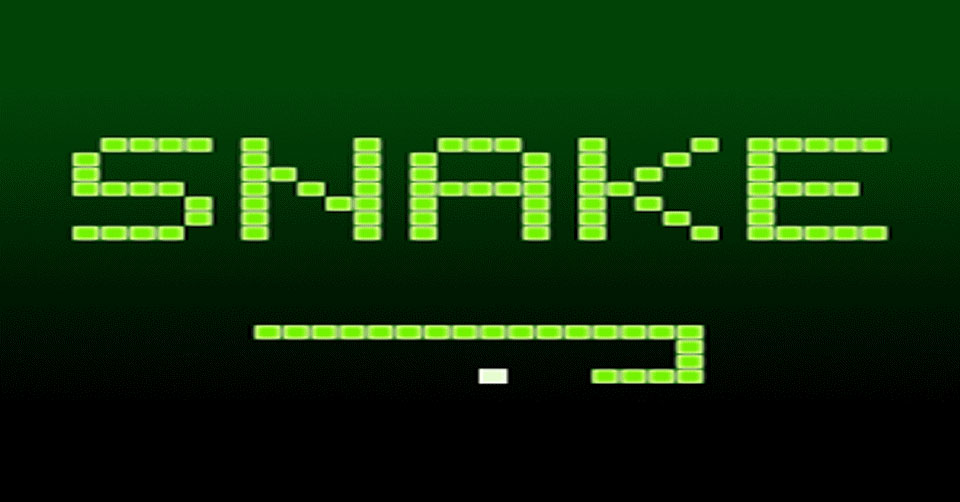
'Snake' game using the library LCD5110_Graph.h.
When it comes to the selection of materials, you can refer to Apogeeweb Electronics
I won't go deep into programming but if you want to design other games you can do it.
3D Printing
Get 3D printed shell. I recommend printing the game console shell first, and then select the hardware that matches the shell. I use Freecad for 3D design and share these files under a CC license. The printing includes four parts: the front of the case, the back of the case, the logo of Gameboy5110, and the bottom. If the prototype board or hardware you choose is different from mine, please change the design drawing according to your plan.
Hardware Parts
1. Motherboard
a. I use a prototype board similar in size to Arduino Nano and LCD.
b. Solder two 15-pin busbars to the prototype board at the same distance as the Arduino headers; the other 8-pin busbar is used to connect to the LCD.
c. Solder the 8-pin busbar to the D3, D4, D5, D6, and D7 pins of the Arduino.
d. The remaining 3 pins are VCC, BL and GND. Solder VCC and BL to any 5V pin, and solder GND to any ground terminal of the circuit board.
During the process, pay attention to the use of female header pins, which is convenient for removing the Arduino and screen or replacing the hardware at any time without damaging any parts. Finally, connect the LCD and DuPont wire as an extender.
2. Left Button
Now, start to install the arrow keys on the left side of the game console. Among them, the resistor is optional. You can use the INPUT_PULLUP (PIN) wire as the internal resistance of the Arduino input, but you need to change the program code.
The connection method of the buttons is as follows:
Weld the four buttons according to the distance shown in the 3D file, or adjust the distance according to the hardware you choose.
To use an analog input as an electronic value, simply define it as an input.
The green wire needs to be soldered to the Arduino input wire. The soldering method is:
Up – Pin 16 (A2)
Left – Pin 17 (A3)
Bottom – Pin 18 (A4)
Right –Pin 19 (A5)
In addition, you need to solder VCC to 5V, and solder GND to any ground terminal of the main prototype board.
Reminder: I recommend soldering longer wires between the prototype boards to better adjust the part position.
3. Right Button
Start to install the button on the right. If you use internal resistance, the following will explain how to use INPUT_PULLUP.
Use the upper right button as the reset button, solder one side to the RST pin of the motherboard, and solder the other side to GND.
The game I currently install does not require a second button, but for the convenience of playing other games in the future, second button is necessary. You only need to solder one side to A1 and the other side to GND. When you use it, it is recommended to use INPUT_PULLUP(15), and use it with digital Read.
4. Power and Switch
This part requires 9v battery, slide switch and battery compartment.
Solder the black wire to GND and the red wire to VIN, but before adding the switch, solder the red wire of the battery compartment to the middle pin of the switch and the other pin to VIN, then close the circuit.
5. Buzzer
You can use your favorite sound unit, here I use the sound generator on the picture-piezoelectric buzzer.
Solder one wire to GND and the other wire to pin 2. Of course you can also change the way of welding.
Finally, use a hot glue gun to fix it on the back of the battery compartment, and now the game console can emit sound.
Parts Installation
1. Fixed Shell
The hardware part of the game console has been completed, and now the shell can be installed. Use solder dots to soften the plastic slightly and insert the nuts into the four fixing posts.
2. Install LCD and slide switch
Install the LCD display, and then use a heat gun to fix it.
Install the slide switch and tighten it with a nut.
3. Install buttons
This part is more complicated. The keys need to be installed in their respective holes accurately and firmly. In order to ensure that the position of the button is not in the state where the button is pressed, the following processing needs to be done.
As shown in the following picture, I inserted a soft plastic sticker and glued it to the button so that it can maintain a spa of a few centimeters.
When you find a suitable position with the prototype board, you can use a hot melt gun to fix it, and pay attention to keep it dry during operation. Both prototype boards need to be treated the same.
After completion, test all the keys to ensure that the installation is correct.
4. Adjust and Modify the Shell
Repair the printed plastic sheet to make it stronger so that the plastic sheet will not squeeze the prototype board deeper when pressed by an external force. Adjustment should be taken in the middle of the two boards.
Then use a hot glue gun to fix it, and then install the battery compartment in the remaining available space after drying. Next, adjust all the wires and the motherboard inside the shell, and close the shell.
Finally, use glue to paste the GameBoy 5110 logo on the bottom of the screen and paint it in your favorite color.
Specific operational physical figures are at the bottom of the projects.
Now you can start!