How to make a Sensitive homemade Lightning detector based on cheap AM Receiver IC TA7642 and Arduino Nano
A lightning detector is a device that detects lightning produced by thunderstorms.
In one of my previous videos, I showed you how to make such a detector with the help of the AS3935 sensor board which is specially designed for this purpose. This time I will show you how to make same such device, but now with a homemade detector circuit based on cheap AM Receiver IC TA7642.
This design is many times cheaper, its sensitivity is much higher, and Also the resistance to local disturbances as various sparks from electrical devices is very high. The ingenious idea of using AM receiver IC as a detector is presented on elektronik-labor.de page under the name "The Franzis thunderstorm warner". The basic Arduino code is taken from Ramser-elektro, and I modified it by adding an active Buzzer and some other small changes.
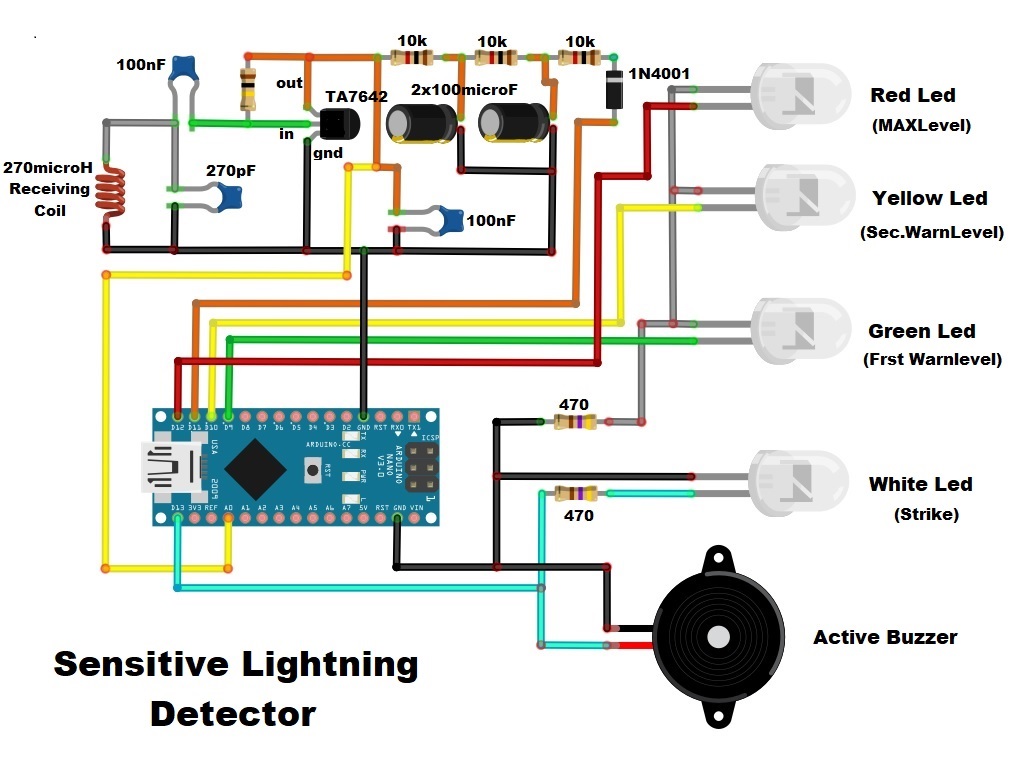
The device is relatively simple to build and contains several parts:
- Arduino Nano microcontroller
- four LEDs for a visual indication with resistors
- active buzzer as an audio indicator
- and small galvanometer also for visual indication
The detector works in the following way: The radio waves from the lightning are received, pre-amplified, demodulated and amplified by the TA7642. Then the output is routed to the analog input A0 of the Arduino. This results in a "voltage drop" in the voltage at the A0 Arduino input per lightning discharge. The more "voltage drops" at the analog input, the more discharges, the closer the thunderstorm.
The sensitivity of the device as well as the resistance to disturbance can be changed in the following two lines of code:
PWM_DutyCycle = (PWM_DutyCycle /3 ) * 2; // PWM value is set to 2/3, for more sensivity 5/6 or 8/9
if (Difference> = 15) { // Would test 12 times there.
The way the device works is: When starting, the voltage of the TA7642 is increased until a certain basic voltage is applied. This is indicated by turning on all the LEDs one by one and finally when all are turned off the device is ready for detection. We perform a thunder simulation with a piezo lighter. The device detects the spark from the piezo lighter at a distance of 1 meter and more. In real conditions, depending on the strength of the lightning, the range reaches up to hundred kilometers. Electrical discharge detection is indicated by a flashing white LED and a short beep from the piezo booster. There is also a small analog instrument whose arrow deflects with each lightning strike.
If a certain number of electrical discharges occur per unit time, the green LED starts flashing and this is the first level of warning. This means that the storm is close to our region. If the discharges continue, the yellow LED starts flashing, which indicates the second level of warning, and the storm is gradually approaching. Finally, if the red LED flashes, a third level warning is activated, which means that our region is hit by a storm. By reducing the frequency of electrical discharges, the warning level is automatically reduced.
The device is installed in a suitable box made of PVC with a thickness of 5 mm, which is coated with colored wallpaper.
// Firmware for Blitz-o-shield Rev.1
// Firmwareversion: Rev.0
// Copyright F.R. 2019
// www.ramser-elektro.at
//
//
#include <Wire.h>

const bool SendFullDebugText = true;         // Send debug message over RS232?
const word RemoteImpulseTime = 000;           // Set how long the remote impulse will be

int LED_red = 12;
int LED_yellow = 10;
int LED_green = 9;
int LED_strike = 13;

int PWM_pin = 11;
int REMOTE_pin = 7;

int AnalogIn = A0;

word ActValue;                                // Actual value of analog signal
float AverageValue;                           // Averange value
int Difference;                               // Difference value (AverageValue - ActValue)

word StrikeCount;                             // Actual strikecounter. Every strike 32 is added.
word WarnLevel = 255;                         // Actual warning level
word Decay;                                    // Value, how much the warnlevel is decreased, if no activity

word InactivityTimer;                         // Timer for new PWM tune, if no activity

bool Blink;                                   // Helper for LED blinking

unsigned long PreviousRemoteMillis = 0;       // Helper for remote impulse

word PWM_DutyCycle;                           // Actual duty cycle for PWM
word PWM_Duty_Watchdog;                       // Helper for PWM Adjustment

unsigned long PreviousMillis = 0;             // Helper for 1 second cycle

void setup(){                                 // Assign the hardware setup

  pinMode(LED_red, OUTPUT);
  pinMode(LED_yellow, OUTPUT);
  pinMode(LED_green, OUTPUT);
  pinMode(LED_strike, OUTPUT);
  pinMode(PWM_pin, OUTPUT);
  pinMode(REMOTE_pin, OUTPUT);
  Serial.begin(9600);
  analogReference(INTERNAL);                  // Set the reference voltage to 1.1 volt
  TunePWM();
}

void TunePWM(){                               // Setup the PWM and tune it
  if (SendFullDebugText){
    Serial.print("PWM duty cycle tuning started");
    Serial.print("\r\n");
  }
  PWM_DutyCycle = 0;                          // First discharge the capaciators
  analogWrite(PWM_pin,PWM_DutyCycle);
  digitalWrite(LED_green, HIGH);              // Set green LED = capaciator discharged
  delay(250);

  ActValue = analogRead(AnalogIn);            // Read dummy
  PWM_Duty_Watchdog = 0;                      // Reset watchdog

  while (ActValue < 1023){                    // Has analogue input reached the maximum?
    ActValue = analogRead(AnalogIn);          // Read analog input
    AverageValue = ActValue;                  // Preset avarange value
    PWM_DutyCycle = PWM_DutyCycle +1;         // Increase PWM level
    PWM_Duty_Watchdog = PWM_Duty_Watchdog +1; // Increase the PWM watchdog
    analogWrite(PWM_pin,PWM_DutyCycle);
    delay(250);                               // Always wait a little time, to load the capacitors
    if (ActValue > 341){                      // Set yellow LED = ActValue  > 1/3 of maximum.
      digitalWrite(LED_yellow, HIGH);
    }
    if (ActValue > 682){                      // Set red LED = ActValue  > 2/3 of maximum.
      digitalWrite(LED_red, HIGH);
    }
    if (PWM_Duty_Watchdog >= 255){            // Maximum PWM duty cycle reached. Something is wrong!!
      Blink = !Blink;                         // LED Blink Helper
      if (SendFullDebugText){
      Serial.print("Problem while adjust PWM Duty cycle. Maximum reached!!!");
      Serial.print("\r\n");
      }
      digitalWrite(LED_green, Blink);         // Blink all LED in endless loop
      digitalWrite(LED_yellow, Blink);
      digitalWrite(LED_red, Blink);
      digitalWrite(LED_strike, Blink);
      delay(500);
    }
    ActValue = analogRead(AnalogIn);          // Read analog input
    AverageValue = ActValue;                  // Preset avarange value
  }

  PWM_DutyCycle = (PWM_DutyCycle /3 ) * 2;
  analogWrite(PWM_pin,PWM_DutyCycle);
  digitalWrite(LED_strike, HIGH);           // Set white LED = Tune PWM successful
  delay(1000);
  digitalWrite(LED_green, LOW);
  digitalWrite(LED_yellow, LOW);
  digitalWrite(LED_red, LOW);
  digitalWrite(LED_strike, LOW);
  if (SendFullDebugText){
    Serial.print("PWM duty cycle tune successfull");
    Serial.print("\r\n");
  }
}

void loop(){

  ActValue = analogRead(AnalogIn);            // Read in actual value
  AverageValue = AverageValue * 15;           // Calculate the averange value
  AverageValue = AverageValue + ActValue;
  AverageValue = AverageValue / 16;
  Difference = AverageValue - ActValue;

if (Difference >= 15){                        // STRIKE !!!
  digitalWrite(LED_strike, HIGH);
  delay(50);
  digitalWrite(REMOTE_pin, HIGH);  // Set remote action

  PreviousRemoteMillis = millis();
  StrikeCount = StrikeCount + 32;
  if (StrikeCount >= 255){                    //  More then 8 Strikes in 1 Second ?
    StrikeCount = 255;                        //  More then 8 strikes per second don't happen naturaly
  }
}
else{
  digitalWrite(LED_strike, LOW);
}

if ((millis() - PreviousRemoteMillis >= RemoteImpulseTime) and (digitalRead(REMOTE_pin))){  // Remote impulse time elapsed
  digitalWrite(REMOTE_pin, LOW);
}

if (millis() - PreviousMillis >= 1000){       // 1 Second elapsed
  Blink = !Blink;                             // LED Blink Helper

  if (StrikeCount > 32){                      // At leased 2 strikes in one second
    WarnLevel = WarnLevel + StrikeCount;      // Increase Warnlevel
  }

  Decay = highByte(WarnLevel);
  WarnLevel = WarnLevel - Decay;              //  Level decreasing

  if (WarnLevel < 1000){                      // No LED on
    digitalWrite(LED_green, LOW);
    digitalWrite(LED_yellow, LOW);
    digitalWrite(LED_red, LOW);
  }
  if ((WarnLevel >= 1000) and (WarnLevel < 1500)){ // Green LED on
    digitalWrite(LED_green, Blink);
    digitalWrite(LED_yellow, LOW);
    digitalWrite(LED_red, LOW);
  }
  if ((WarnLevel >= 1500) and (WarnLevel < 2500)){ // Yellow LED on
    digitalWrite(LED_green, LOW);
    digitalWrite(LED_yellow, Blink);
    digitalWrite(LED_red, LOW);
  }
  if (WarnLevel >= 2500){                     // Red LED on
    digitalWrite(LED_green, LOW);
    digitalWrite(LED_yellow, LOW);
    digitalWrite(LED_red, Blink);
  }
  if (WarnLevel >= 3000){                     // Maximum reached
    WarnLevel = 30000;
  }

  if (SendFullDebugText == true){             // Send debugmessage over RS232
    // PWM;ActValue;AverangeValue;Difference;Warnlevel;Decay;Strikecount;
    Serial.print("PWM:");
    Serial.print(PWM_DutyCycle);
    Serial.print("  Actual:");
    Serial.print(ActValue);
    Serial.print("  Averange:");
    Serial.print(AverageValue);
    Serial.print("  Difference:");
    Serial.print(Difference);
    Serial.print("  Warnlevel:");
    Serial.print(WarnLevel);
    Serial.print("  Decay:");
    Serial.print(Decay);
    Serial.print("  Strikecount:");
    Serial.print(StrikeCount);
    Serial.print("\r\n");
  }

  if (Decay == 0){                            // No activity. Increase InactivityTimer
    InactivityTimer = InactivityTimer +1;
    if (InactivityTimer >= 3600){             // No activity for one hour. Tune PWM.
      TunePWM();
      InactivityTimer = 0;
    }
  }

  StrikeCount = 0;                            // Reset strikecounter
  PreviousMillis = millis();                  // Save actual millis, for the next 1 second cycle
}

}