LED Matrix that is determined by the output of a retroreflective sensor
The goal of this project was find a way to visually represent how long an object had been in a nearby location for. I was in charge of prototyping, designing, building and testing the system.
Customer & Technical Requirements
Customer: When the object comes into frame
1. Timer begins
2. Continues until the object leaves
3. Resets the timer until another object comes in
Technical:
1. A sensor will need to detect when the object comes
2. LCD must be located to be clearly visible
3. Logic device must be integrated
4. Must be able to withstand able in industrial environment
Design & Build- 1st Iteration
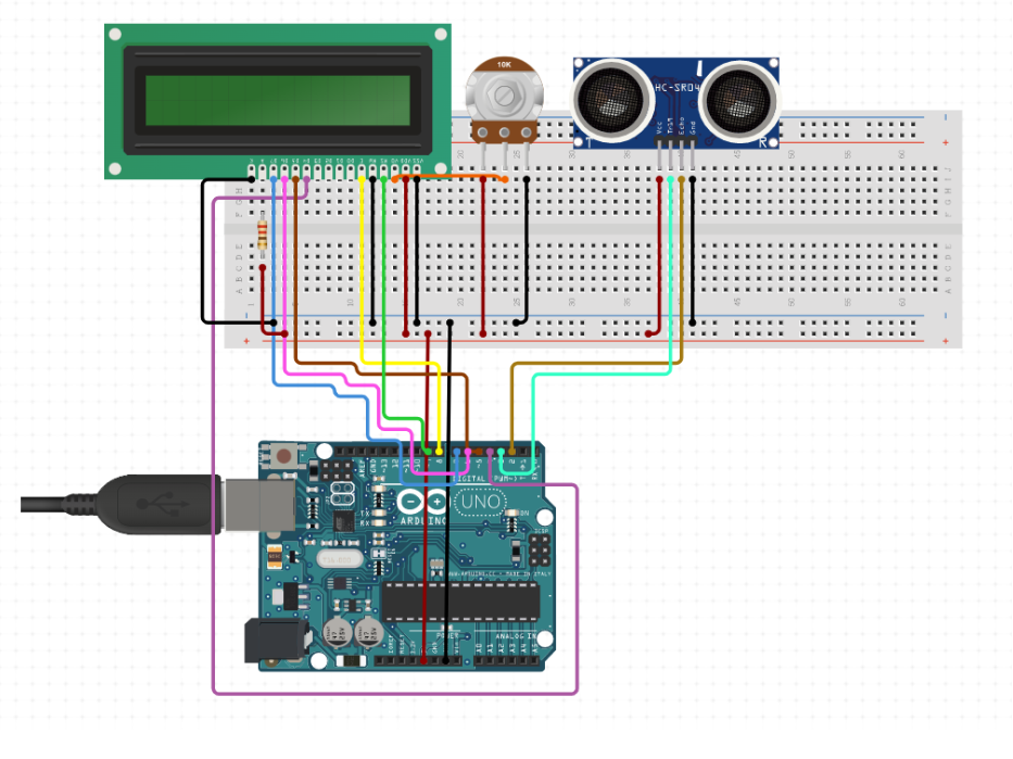
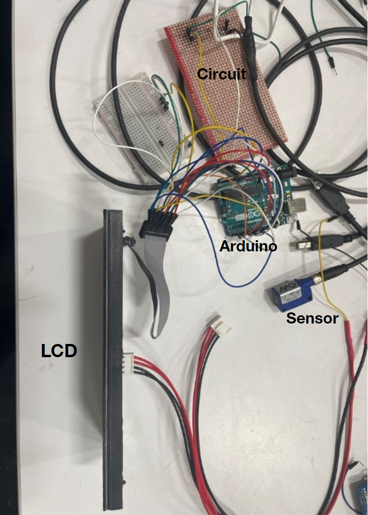
I decided for my development board I would use an Arduino (good for taking sensors as real time inputs). For my visual aid I went with an LCD (good interface with Arduino) and for my sensor I went with the HR-074 Ultrasonic sensor (measures distance in a lab environment well).
Figure 1. Wiring diagram for 1st iteration
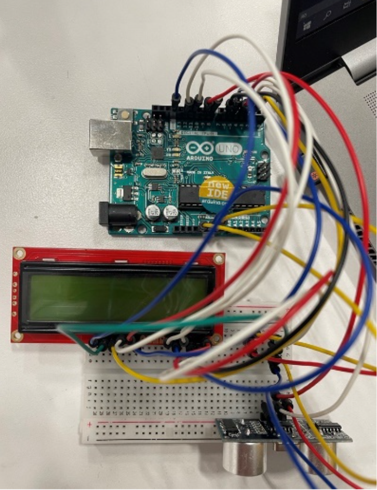
Figure 2. Live image of setup
#include <RGBmatrixPanel.h>

int seconds;
int input_pin = 11;
int output_pin = 0;

// Most of the signal pins are configurable, but the CLK pin has some
// special constraints.  On 8-bit AVR boards it must be on PORTB...
// Pin 8 works on the Arduino Uno & compatibles (e.g. Adafruit Metro),
// Pin 11 works on the Arduino Mega.  On 32-bit SAMD boards it must be
// on the same PORT as the RGB data pins (D2-D7)...
// Pin 8 works on the Adafruit Metro M0 or Arduino Zero,
// Pin A4 works on the Adafruit Metro M4 (if using the Adafruit RGB
// Matrix Shield, cut trace between CLK pads and run a wire to A4).

#define CLK  8   // USE THIS ON ARDUINO UNO, ADAFRUIT METRO M0, etc.
//#define CLK A4 // USE THIS ON METRO M4 (not M0)
//#define CLK 11 // USE THIS ON ARDUINO MEGA
#define OE   9
#define LAT 10
#define A   A0
#define B   A1
#define C   A2
#define echoPin 11 // attach pin D2 Arduino to pin Echo of HC-SR04
#define trigPin 12 //attach pin D3 Arduino to pin Trig of HC-SR04

// defines variables
long duration; // variable for the duration of sound wave travel
int distance; // variable for the distance measurement

RGBmatrixPanel matrix(A, B, C, CLK, LAT, OE, false);


void setup() {
  pinMode(trigPin, OUTPUT); // Sets the trigPin as an OUTPUT
  pinMode(echoPin, INPUT); // Sets the echoPin as an INPUT
  Serial.begin(9600); // // Serial Communication is starting with 9600 of baudrate speed
  Serial.println("Ultrasonic Sensor HC-SR04 Test"); // print some text in Serial Monitor
  Serial.println("with Arduino UNO R3");
  matrix.begin();
  // draw a pixel in white

}

void loop() {

    // Clears the trigPin condition
    digitalWrite(trigPin, LOW);
    delayMicroseconds(2);
    // Sets the trigPin HIGH (ACTIVE) for 10 microseconds
    digitalWrite(trigPin, HIGH);
    delayMicroseconds(10);
    digitalWrite(trigPin, LOW);
    // Reads the echoPin, returns the sound wave travel time in microseconds
    duration = pulseIn(echoPin, HIGH);
    // Calculating the distance
    distance = duration * 0.034 / 2; // Speed of sound wave divided by 2 (go and back)
    // Displays the distance on the Serial Monitor
    Serial.print("Distance: ");
    Serial.print(distance);
    Serial.println(" cm");
    Serial.begin(9600);

    if (distance < 100) {
      matrix.print(seconds);
      Serial.println(seconds);
      delay(1000); // do not change!!!!!
      if (seconds < 9) {
        matrix.setCursor(12, 0);  // start at middle, with one pixel of spacing
      } else if (seconds > 8 && seconds < 99){
        matrix.setCursor(5, 0);  // start at , with one pixel of spacing
      } else if (seconds > 98 || seconds == 100) {
        matrix.setTextSize(1.5);   // size 1 == 8 pixels high
        matrix.setCursor(8, 0);  // start at left side, with one pixel of spacing
        matrix.setTextColor(matrix.Color333(7,0,0));
      }
      matrix.fillScreen(matrix.Color333(0, 0, 0));
      seconds++;
    } else {
        matrix.setCursor(12, 0);  // start at top left, with one pixel of spacing
        matrix.setTextSize(2);   // size 1 == 8 pixels high
        matrix.setTextColor(matrix.Color333(7,7,0));
        matrix.print('0');
    }
}
Changes Made
The problems with the 1st design were that the 16x2 backlight display was too small and the ultrasonic sensor was not robust enough.
The changes that were made were:
1. Changing the ultrasonic sensor to an industrial grade retroreflective sensor
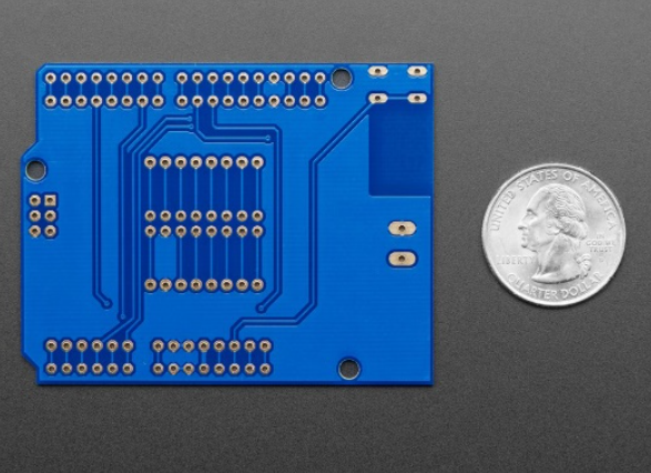
2. Adding a PCB to the Arduino to limit the amount of wiring
3. Changing the 16x2 Backlight display to a 16x32 LED Matrix
2nd Iteration- Design & Build
In this iteration, I used a retroreflective industrial sensor with an Arduino and a 16x32 LED Matrix. I ran into troubles interfacing the industrial grade sensor since it required 10-30 VDC while an Arduino can only output 5V. I had to externally power the sensor then design a circuit for the system.
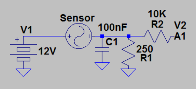
Figure 3. Circuit designed to interact with Arduino input pins
The circuit was modelled and tested using LT Spice before adding it to the breadboard. I found out the sensor outputted a varying current (4-20 mA) and not a varying voltage, so I had to mess around with a few different options.
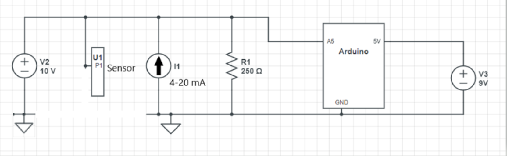
Figure 4. Revised circuit with Arduino and ground connections
#include <TimeLib.h>
#include <RGBmatrixPanel.h>
#include <EEPROM.h>

// Most of the signal pins are configurable, but the CLK pin has some
// special constraints.  On 8-bit AVR boards it must be on PORTB...
// Pin 8 works on the Arduino Uno & compatibles (e.g. Adafruit Metro),
// Pin 11 works on the Arduino Mega.  On 32-bit SAMD boards it must be
// on the same PORT as the RGB data pins (D2-D7)...
// Pin 8 works on the Adafruit Metro M0 or Arduino Zero,
// Pin A4 works on the Adafruit Metro M4 (if using the Adafruit RGB
// Matrix Shield, cut trace between CLK pads and run a wire to A4).

#define CLK  8   // USE THIS ON ARDUINO UNO, ADAFRUIT METRO M0, etc.
//#define CLK A4 // USE THIS ON METRO M4 (not M0)
//#define CLK 11 // USE THIS ON ARDUINO MEGA
#define OE   9
#define LAT 10
#define A   A0
#define B   A1
#define C   A2
//#define D   A3

# define TRUE 1
# define FALSE 0

#define TIME_HEADER  "T"   // Header tag for serial time sync message
#define TIME_REQUEST  7    // ASCII bell character requests a time sync message

int potPen = A5;
int readValue;
int seconds;
float voltage;

int timeValues[50];
byte arrayIndex = 0;

int counterValues[50];
byte arrayIndex2 = 0;

int address = 0;

RGBmatrixPanel matrix(A, B, C, CLK, LAT, OE, false);

void setup() {
  pinMode(potPen, INPUT);
  Serial.begin(9600);

  setSyncProvider( requestSync);  //set function to call when sync required
  Serial.println("Waiting for sync message");

  matrix.begin();

  // fix the screen with green
  matrix.fillRect(0, 0, 32, 16, matrix.Color333(0, 7, 0));
  delay(500);

  matrix.setCursor(12, 0);  // start at top left, with one pixel of spacing
  matrix.setTextSize(2);   // size 1 == 8 pixels high
  matrix.setTextColor(matrix.Color333(7,7,0));
  matrix.fillScreen(matrix.Color333(0, 0, 0));

}

void loop() {

    if (Serial.available()) {
    processSyncMessage();
    }
    if (timeStatus()!= timeNotSet) {
      digitalClockDisplay();
    }

    readValue = analogRead(potPen);
    voltage = (5./1023)*readValue;
    //Serial.println(voltage);

    if (voltage > 1) {
      matrix.print(seconds);
      Serial.println(seconds);
      delay(1000); // do not change!!!!!
      if (seconds < 9) {
        matrix.setCursor(12, 0);  // start at middle, with one pixel of spacing
      } else if (seconds > 8 && seconds < 99){
        matrix.setCursor(5, 0);  // start at , with one pixel of spacing
      } else if (seconds > 98 || seconds == 100) {
        matrix.setTextSize(1);   // size 1 == 8 pixels high
        matrix.setCursor(7, 0);  // start at left side, with one pixel of spacing
        matrix.setTextColor(matrix.Color333(7,0,0));
      } else if (seconds > 40) {
        //counterValues[arrayIndex] = seconds;
        //timeValues[arrayIndex2] = digits;
        EEPROM.update(address,seconds);
      }
      matrix.fillScreen(matrix.Color333(0, 0, 0));
      seconds++;
    }
    else {
        matrix.setCursor(12, 0);  // start at top left, with one pixel of spacing
        matrix.setTextSize(2);   // size 1 == 8 pixels high
        //matrix.setTextColor(matrix.Color333(7,7,0));
        seconds = 0;
        matrix.print('0');
    }

}
The analog pin 5 on the Arduino reads the voltage across the resistors, then depending on that value it will begin an up counter (which is controlled in the loop block).
Figure 6. Added PCB to Arduino to make wiring connections cleaner
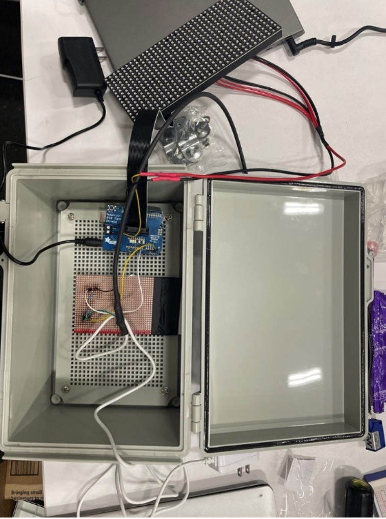
Figure 7. Whole system with Arduino shield
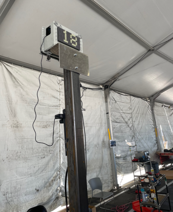
Figure 8. Final system constructed with brackets (electronic are inside the enclosure)
Results
It worked! The sensor was able to detect when an object was there and would initiate a timer reflected on the LED Matrix.