Making of automatic induction door based on Arduino
Step 1: Obtain and install the motor
Motor selection
First, we need a voter ic motor. It is very important that the motor has a large torque and a low speed. This is why I use a wiper motor. Any wiper motor in any car can be used. You can also use another DC motor around, but make sure it has enough torque to move the door.
Electric motor power supply
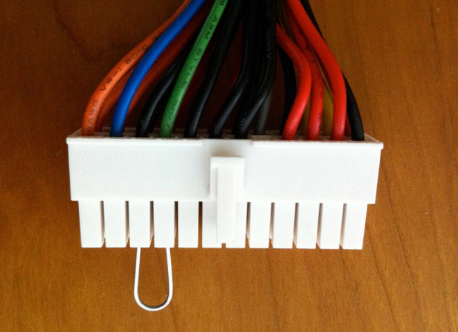
The 12 V DC motor I use can use up to 12 A. This is why it is so sturdy but now it needs a powerful power supply to power it. That's the use of computer power. I am using a 300 watt power supply, but a lower/higher power supply can also work. It will provide 12 A on its 12 V power rail, which is sufficient for our DC motors. To get power from it, we must first short-circuit the green wire with the black wire. This will act as the power button. Without it, the power supply will not start. Check the picture above to see the wires and how to short them.
Door mechanism
To open the door, we need to build an institution. Check out the picture above. It consists of two metal sheets. One is 20 cm and the other is 25 cm long. It may also be made of wood, but I am not sure of its strength. It is important to have two points that can be moved. One is where the two parts are connected to each other, and the other is where the longer part is connected to the doorpost. The other side of the smaller part needs to be mounted on the motor. Because I used metal parts, I welded them to the motor. It sounds unclear, but if you watch the video, everything will become clear.
Install
After making the mechanism, you need to install it on your door. To do this, I first screw some screws into the top of the motor that needs to be rotated. Then I got some zippers and fixed the motor to these screws with zippers. After that, I used a lot of hot glue to add complexity. I have installed the motor about 10 cm on the right side of the center of the door, and installed the long block of the mechanism about 2 cm on the right side of the center of the door post.
This is the hardest part of the project. If you find that the motor does not have enough power to open the door or the door cannot be fully opened, try changing the position of the motor or changing the length of the mechanism.
Step 2: Prepare the Arduino
I am using the brain of the Arduino UNO project. Any other Arduino compatible device can work like Arduino nano.
We first need to download the code that can be found on my github:
https://github.com/sieuwe1/AutomaticDoor
Click the Clone/download button, and then click "Download as ZIP".
Then unzip the software package and use the Arduino IDE to open the AutomaticDoor.ino file.
Then upload the code to the arduino board
In the Arduino IDE, you can see the code. There is a configuration section in the code above, just like the picture above. A very important variable is the MotorDelay variable. This determines how long the motor will gain power. The longer the variable, the longer the motor turns, and the longer the motor turns, the more times the door opens. Therefore, if the door is not fully opened or shattered into something, because if the door is opened too much, change this variable. Then upload the code again to see if it works now.
Step 3: Make the controller and connect everything
H bridge
To control the movement of a DC motor, we must build a motor controller. For this, we use the H-bridge configuration in the figure above. I have built an H-bridge using 5v relays, but you can also use 4 N-channel MOSFETs. Build it like the schematic above, and make sure to use thick wires and high amperage components. If you are using mosfet, I suggest you use IRFZ44n because they are logic level operation.
After the H-bridge is completed, we need to connect a few wires. Connect the coil pins of the relay (the second picture below) to A1 and B2 and B1 and A2 together. If you want to make a mosfet H bridge, connect the gate pins together like in a relay H bridge.
Schematic diagram
Now that we have the H-bridge, we need to connect it to the Arduino. Follow the schematic in the picture and connect everything else to it.
If you have everything connected, place an ultrasonic sensor on one side of the door and the other side on the other side.
If the door needs to be closed or otherwise opened when it is closed, switch the wires on pins 8 and 9.
Step 4: Finish
Hope this is not difficult. If you have completed all the correct operations, you will now have your own SciFi door!


