You can use Arduino to turn on LED when we press a button. A switch is a electrical component that completes a circuit when pushed & breaks.
About Project
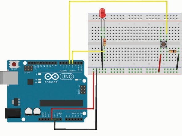
Build your Arduino circuit by looking at the breadboard designing image above or as per description mentioned below. Here letters and symbols combined structure indicate that combination of column and row.
Step 1 – Connect the blue jumper wire from the GND on the Arduino to the GND blue rail on the breadboard near column A & row 13.
Step 2 – Connect the blue jumper wire from the GND rail on the breadboard near Column A & row 17 and to the H Column 17th row.
Step 3 – Connect the red jumper wire from the power rail on the breadboard around row A column 27th row and to the column H row 26th.
Step 4 – Connect the green jumper wire from pin 2 on Arduino to J24 on the breadboard.
Step 5 – Place one side leg of 10k Ohm resistor in G19 and the other side in G24
Step 6 – Locate the push button switch into F24, F26, E24 and E26
Step 7 – Place one side of leg of 220 Ohm resistor in D5 and the other leg in G5
Step 8 – Insert the short leg of the LED in the GND rail around A5 and the long leg in B5
Step 9 – Join the black jumper wire from pin 13 on the Arduino to I5 on the breadboard.
Step 10 – Attach the red jumper wire from 5V on the Arduino to power rail (+) near A8.
Step 11 – Attach the Arduino Uno to your computer using USB cable.
Upload the sketch to the Arduino that will allow us to use a switch.
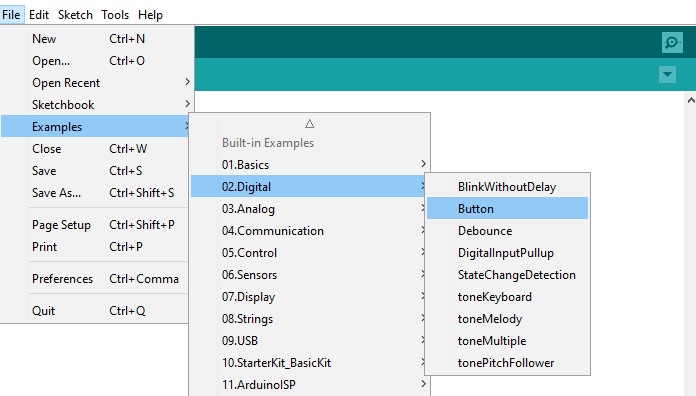
In order to utilize a switch, we have to load the file called “Button” which can be seen here: File > Examples > Digital > Button
Next, you need to click on the check mark that is placed in the top left of the IDE box. Once it shows “Done Compiling” we are ready to upload it.Click the upload forward arrow to send the program to the Arduino breadboard.
Press the button switch on the breadboard and you should be able to turn on/off the LED. Check the project schematic shown below:
const int switchPin = 4;             //Switch Connected to PIN 4
const int ledPin = 8;                //LED Connected to PIN 8
int switchState = 0;                 // Variable for reading Switch status
void setup()
{
    pinMode(ledPin, OUTPUT);          //LED PIN is Output
    pinMode(switchPin, INPUT);        //Switch PIN is input with PULLUP
}
void loop()
{
    switchState = digitalRead(switchPin);   //Reads the status of the switch.
    if (switchState == LOW)                 //If the switch is pressed
    {
        digitalWrite(ledPin, HIGH);         //LED ON
        delay(3000);                        //3 Second Delay
        digitalWrite(ledPin, LOW);          //LED OFF
    }
}