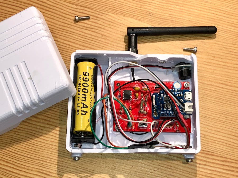
My first project running on a lithium ion battery is here: an IOT device that not only detects if there is water but sends data to the cloud
A friend of mine and I gave each other a little challenge project: We had to create a device that can detect water leak and sends status data over the internet. The challenge included a constraint: I had to use a WEMOS development board. I thought that this project is a good candidate to use a battery so I designed around it. I decided to use an existing battery shield to power up the electronic circuit.
It was my first experience building electronic project using a battery. The result works but, it is a little bit power hungry.
First, check the project in action by looking at the video presentation of that project. Then, I will walk through my circuit to explain how does it work.
When measuring the electronic consumption excluding the WEMOS, we can see that it consumes 1.22ma which is not low enough for a device that works on battery but because I decided to use a 9900mah battery, I expect this circuit to work at least 41 weeks autonomously and I think that it is ok for me as my first project running on battery.
You can download the circuit that I made with Eagle but, to understand it, I decided to explain how I did it in details in the next sections.
The first part is the comparator: the operational amplifier that I use continually compares the point (a) and (b) and reacts when the lead touches water. We know that water is not that conductive so we expect between 400k ohms to 3M ohms and when the detector does not touches water, the point (a) is pulled up by the 3.3M resistor. As soon as the water touches the lead, it pulls to the ground and creates a voltage divider that is compared by the MCP602 with the other voltage divider created by the 2 100K resistors. The result is that the output of the op amp goes to high.
In the second part of my circuit, first there is a capacitor (a) that is used to smooth out the output of the op amp (MCP602). When analyzing the output on my scope, I noticed that, at the moment that the water touches the lead, it may produce some switching between high and low a couple of times before it stabilizes so putting a small cap allows to smooth out the output. Then there is a coupling capacitor (b) that will produce one peak when the output (a) goes to high. it is important not to leave the value to high because the reset must be a single spike and that is the role of this cap. Then when the spike is produced, it triggers the transistor that pulls the voltage down to ground resetting the WEMOS once ( c) and produces a wake up of the controller.
The program (that is not available in this project) is going to check if there is water ( avoiding false reset) by using a digitalRead on pin D6 to read if the voltage at the output of the op amp is high (d) and if so, it really means that the leads are touching water.
The program (that is not available in this project) then posts the information on io.adafruit.com. Adafruit is a FREE service that allows IOT devices to send and read data on feeds using MQTT.
As soon as water is confirm, the WEMOS triggers the buzzer via pin D7 (a). I had an old RC Buzzer. The buzzer is quite loud and very simple to use, it only needs a value HIGH to fire and automatically horn buzzer 3 times. Then, the program (that is not available in this project) writes a value in the EEPROM of the WEMOS and goes to deep sleep for a period of 30 seconds. When it wakes up, it reads the EEPROM and knows that water was detected in the past and digitalRead pin D6 again and if it still high, it fires the buzzer again and cycles until water is no longer detected.
This step is important because, the initial wake happens only once. When water is detected, the op amp goes to high and stays to high so the reset does not happen again. My program (that is not available in this project) should be able to rely on timer as well.
Finally, I program (that is not available in this project) 2 boot up sequences:
- a boot up sequence that acts as a wifi client and connect to the cloud to send data
- a boot up sequence that acts as a wifi hotspot so I can connect to it to configure my wifi personal information
As you can see in the next part, I soldered a wire directly from the battery connector to the board (a) so the program (that is not available in this project) can read and calculate the voltage. I calculated the 2 resistors in the voltage divider (b) and then carefully evaluate the voltage value that is sent to the cloud. After booting up, the WEMOS reads pin A0 and evaluates the voltage. The program (that is not available in this project) then sends the calculated value to the cloud.
As I mentioned a couple of time in that project, the program is not available in this project. Sorry but the goal of that post is more about about the electronic circuit than the programming. I am not a programmer and my code is far from being a good example for you.
This being said, I am sure that you can create your own program using the same sources as I did so I share with you the web sites that inspired my programming.
Create A Simple ESP8266 NodeMCU Web Server In Arduino IDE
Input Data on HTML Form ESP32 / ESP8266 Web Server using Arduino IDE
As I mentioned previously, my device sends data on io.adafruit.com. Adafruit makes it easy to freely use an IOT service for that kind of project and I use it a lot.
The dashboard that I made allows me to see the status, the time the WEMOS communicate with the MQTT service and the battery voltage.
Even if this post is more about the electronics, I must mention the way I designed the enclosure.
First, here is a 3D view of what I envisioned when thinking about a leak detector sitting on the concrete near my hot water tank
I designed the enclosure with 3 point. To of them are stainless screws and one of them is part of the plastic cover. in the next images, you can see that I used Barrel Wire Crimp Copper Terminal Connerctor to make the contact with the 2 screw that serves as the legs for my enclosure. I soldered the wires on the copper connector and connect the other end on my circuit.