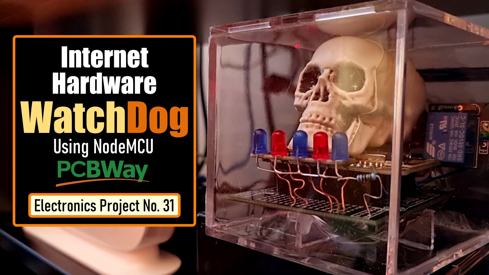
This is an "Internet Hardware Watchdog" that reboots the WiFi router whenever something silly happens to it.
I love mining and I truly believe that blockchain and digital currencies will one day change the world. Cryptocurrency has played a significant role in my life and has made me a morning person, ha ha.
Miners require 24 x 7 access to the Internet. Recently, I went on a short business trip and my router for some stupid reason stopped working. I lost complete access to my home network and my miners. When I returned from my trip, my only aim was to fix this issue by creating an "Internet Hardware Watchdog" that reboots the router whenever something silly happens to it.
Note: If you do any work with "mains power" such as 120v or 240v AC power wiring, you should always use proper equipment and safety gears and determine whether you have adequate skill and experience or consult a Licensed Electrician. This project is not intended for use by children.
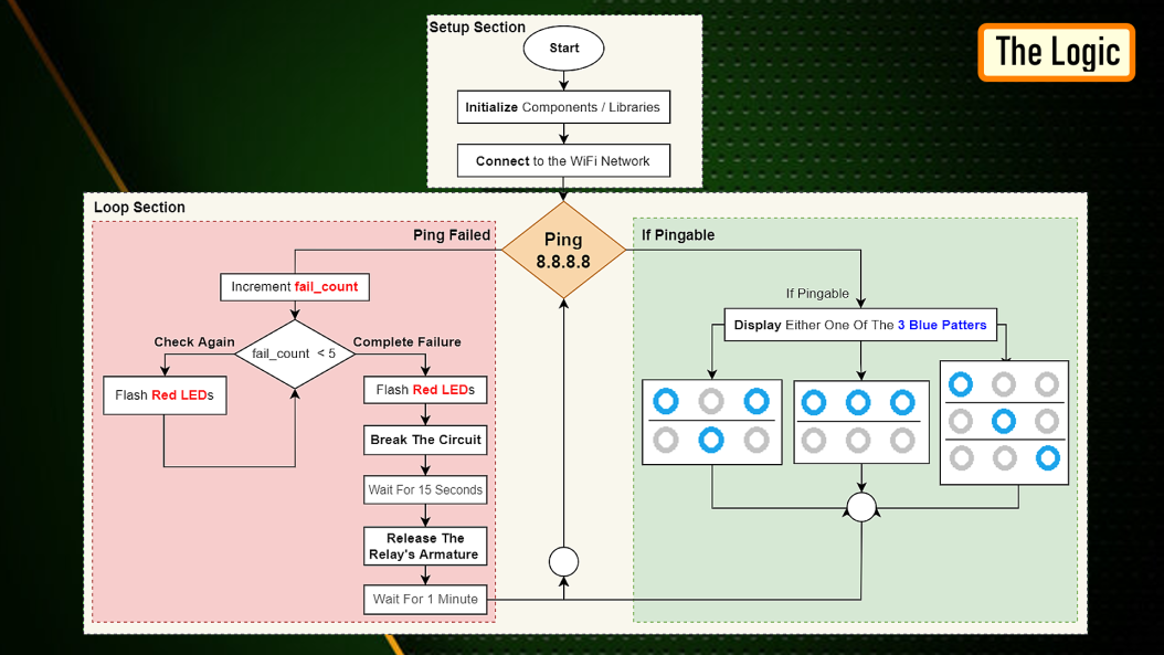
Let me first explain the logic to you. In a nutshell, in this setup I am going to ping "www.google.com" and as soon as the ping drops I will reboot the router.
To achieve this, the NoduMCU first connects to the WiFi network and then pings 8.8.8.8 (www.google.com).
If it receives a successful ping, one out of the 3 blue LED patterns is displayed.
If the ping fails, 5 more retries are given before rebooting the router. The reason I am NOT rebooting the router straightaway is to avoid false positive ping fail responses. However, once the "fail_count" counter becomes 5, NodeMCU turns off the router by pulling the armature of the relay module. The armature of the relay is held for 15 seconds before releasing it so that the router is properly power cycled. Once the armature is released, the system waits for a minute before sending the next ping request. This gives enough time to the router to successfully perform its POST activities.
The above steps are then endlessly repeated in the loop section of the code.
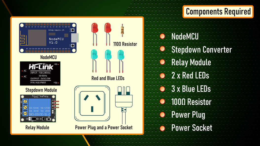
For this project we need:
- NodeMCU
- Stepdown Converter
- Relay Module
- 2 x Red LEDs
- 3 x Blue LEDs
- 100Ω Resistor
- Power Plug and a
- Power Socket
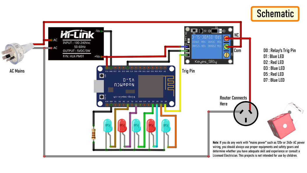
Schematic
Now, let's put the components together exactly the way I have shown in the schematic diagram.
Be very careful while handling AC Main Power sockets and cables.
The Stepdown Converter powers the NodeMCU and the Relay Module. LEDs are connected to the Digital pins of the microcontroller. The relay acts as a switch and switches on or off the router based on the ping response.
Please make sure you check the pins of your relay module before hooking it up to the circuit.
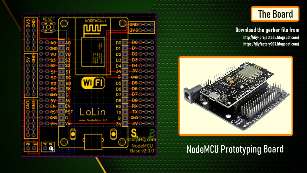
So, this is how my board looks like in 2D and 3D.
I basically have created a replica of the NodeMCU Prototyping Board which you can buy from AliExpress for about $4 to $6.
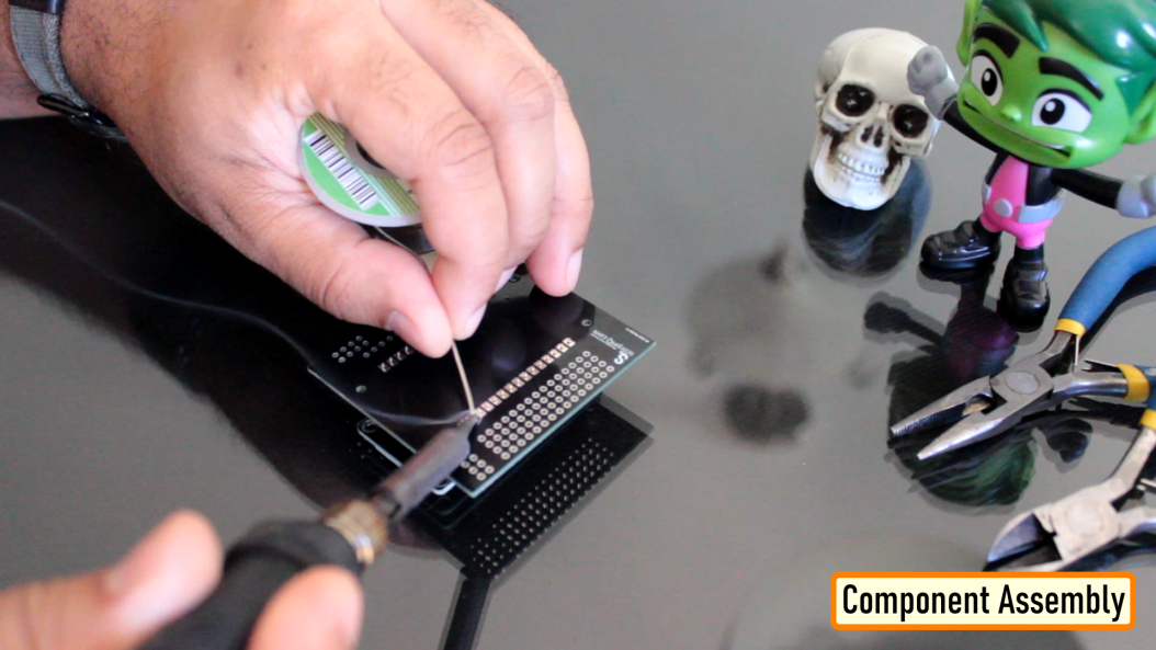
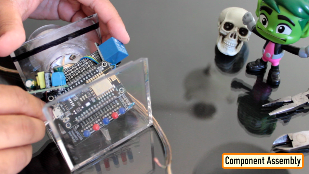
Lets start by soldering the NodeMCU to the board. Since I care a lot about my Sensors and Microcontrollers, I am not going to solder them directly to the board. Instead I am soldering 'female pin headers' to the board which will house all the sensors and the microcontrollers in them.
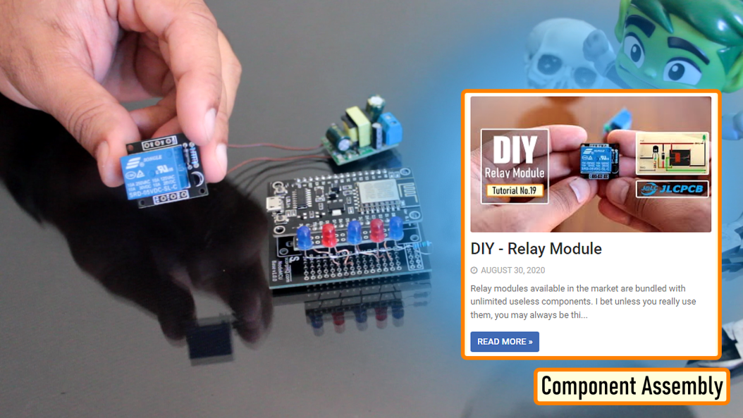
I initially thought of soldering the LEDs directly on the board however something clicked in my mind and I went ahead and soldered them on a separate perfboard and then soldered the perfboard to the NodeMCU development board. Well, this was totally unnecessary.
Once the LEDs were in place, my next step was to solder the step-down-converter and the relay-module to the board. If you want to know how I created this relay module, please check out my tutorial no. 19
DIY Relay Module : https://www.youtube.com/watch?v=3n69b4sdDjk the video and the blog post links are in the description below.
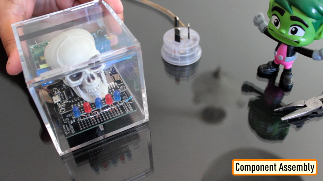
Next, I made a hole in the transparent box and glued the power socket into it. Well I created a bit of mess while gluing the socket and accidentally glued the box on to my dining table, silly me. I also drilled a hole at the back of this box, for the cable that will connect to the AC Main power supply.
Pretty much that's it. Once again, I would like to warn you guys: If you do any work with the "main power" such as 110v or 240v AC, you should always use proper equipment and safety gears and determine whether you have adequate skill and experience or consult a Licensed Electrician. This project is not intended for use by children.
To conclude the setup, I added a small skull inside the acrylic box. This skull has been sitting on my desk just collecting dust for over a year, ha ha.
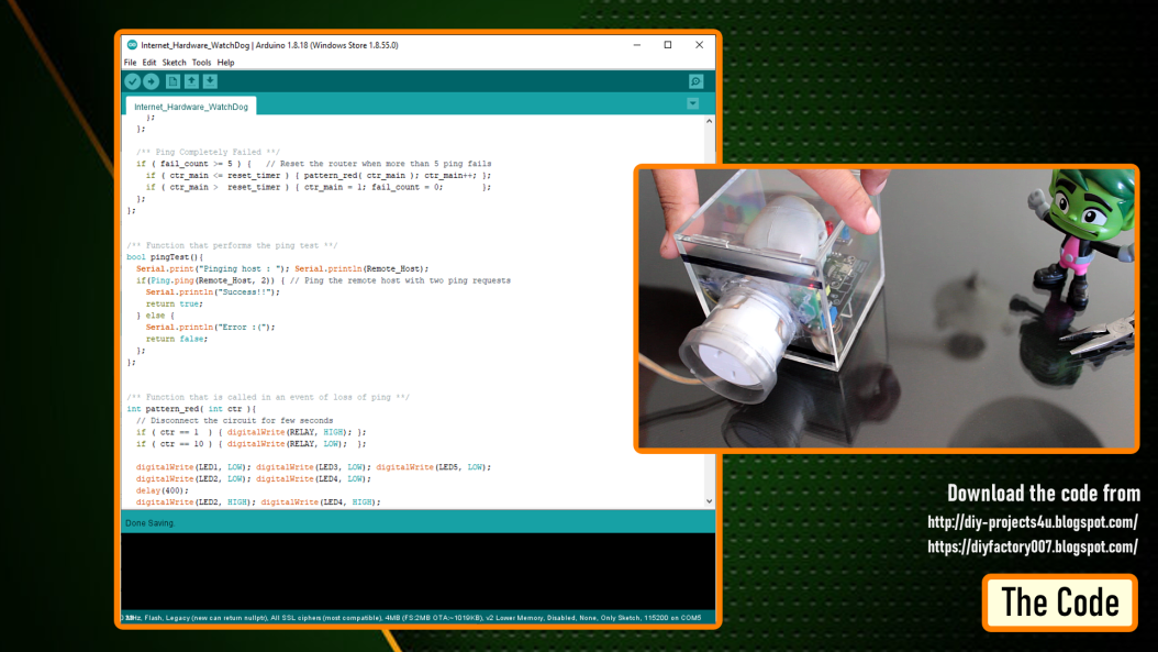
Now, let's have a look at the code. You can download the code and other resources from the links provided in the description below.
To Run the attached code you need to download and install the "ESP8266Ping" library. You can either download it from GitHub or from the link provided in the description below. Unzip and copy the archive to the Arduino's Library Folder and change the board type to ESP8266 in the Arduino IDE and select NodeMCU.
The code starts by including all the libraries and variables on top.
Then in the setup() section I have defined all the pin modes and have made a connection to the WiFi router.
In the loop() section I am performing a ping test and based on the test result I am either blinking the blue LEDs or power cycling the router.
Thanks
Thanks again for checking my post. I hope it helps you.
If you want to support me subscribe to my YouTube Channel: https://www.youtube.com/user/tarantula3
Blog Posts:
Internet Hardware WatchDog : https://diy-projects4u.blogspot.com/2021/12/internet-hardware-watchdog.html
DIY Relay Module : http://diy-projects4u.blogspot.com/2020/08/diy-relay-module.html
Video:
Internet Hardware WatchDog :
DIY Relay Module : https://www.youtube.com/watch?v=3n69b4sdDjk
Other Resources:
Code: https://drive.google.com/file/d/1HyTUMUBDK0neO854XMl3dyy5ceoeTImw/view?usp=sharing
ESP8266Ping Library : https://github.com/dancol90/ESP8266Ping.git
ESP8266Ping Library : https://drive.google.com/file/d/1uFfY5wW7-oWRNjP_XaBj2IM189M1n1FK/view?usp=sharing
Schema: https://drive.google.com/file/d/1gn2ZhMp5Uz4YDv5GjxgIq1rtzh-21Rwe/view?usp=sharing
Gerber File: https://drive.google.com/file/d/1l0bszJ0AV7S9s-y9jTWGcw9MrWayVJxZ/view?usp=sharing
Flowchart: https://drive.google.com/file/d/1CL3g0nT1IZfdL8MZqN_PB-mKC9k_JfWH/view?usp=sharing
Support My Work:
BTC: 1M1PdxVxSTPLoMK91XnvEPksVuAa4J4dDp
LTC: MQFkVkWimYngMwp5SMuSbMP4ADStjysstm
DOGE: DDe7Fws24zf7acZevoT8uERnmisiHwR5st
ETH: 0x939aa4e13ecb4b46663c8017986abc0d204cde60
BAT: 0x939aa4e13ecb4b46663c8017986abc0d204cde60
LBC: bZ8ANEJFsd2MNFfpoxBhtFNPboh7PmD7M2
Thanks, ca again in my next tutorial.