The MP2314 is a high frequency synchronous rectified step-down switch mode converted with built-in internal power MOSFET
In this article, you will learn about how to use MP2314 Buck converter IC in a circuit to power various stuff with it. MP2314 is a powerful synchronous buck converter that takes 6-24V input and converts into 5V 2A Output which is suitable for charging applications and powering applications.
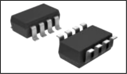
What is a MOSFET?
A metal-oxide-semiconductor field-effect transistor (MOSFET, MOS-FET, or MOSFET) is a field-effect transistor (FET with an insulated gate) where the voltage determines the conductivity of this Transistor. It is mainly used for switching or amplifying signals.
The ability to change conductivity with the amount of applied voltage can be used for amplifying or switching electronic signals. MOSFETs are now even more common than BJTs (bipolar junction transistors) in digital and analog circuits and it is widely used in audio amplifier circuits.
The MP2314 which has a synchronous mode of operation that provides fast transient response and eases loop stabilization.
Features of MP2314 MOSFET
The various features of MP2314 MOSFET are listed below
●It has a wide 4.5V to 24V Operating input range.
●The device also provides a 2A load current.
●The MOSFET is also capable of low quiescent current.
●It has fixed 500hz switching frequency.
●It has AAM power supply mode.
●This MOSFET provides thermal shutdown also.
Applications of MP2314
The various applications are listed below.
This MOSFET is used in notebook systems.
This MOSFET is used in input/output systems.
This MOSFET is used in digital set-top boxes.
This MOSFET is used in flat-panel monitors and televisions.
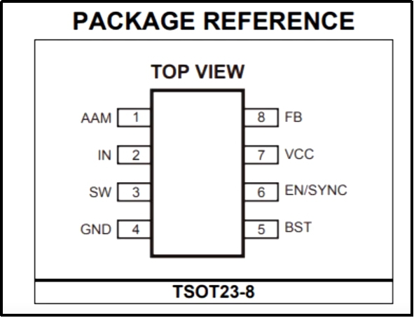
The pinout diagram of the MP2314 is as follows
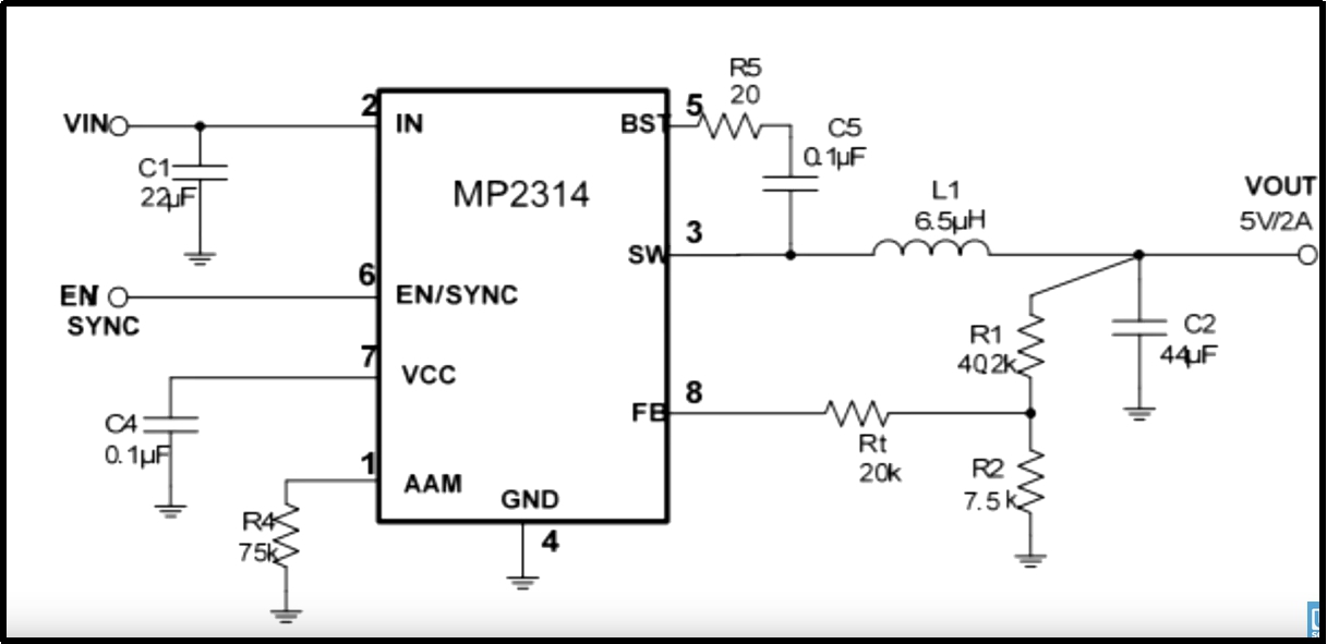
Now we will proceed toward making our desired circuit for the use of the MP2314 just follow the steps below to make it.
First, obtain the schematics from the datasheet.
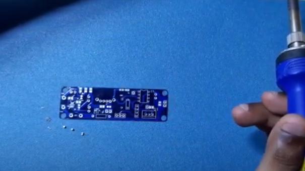
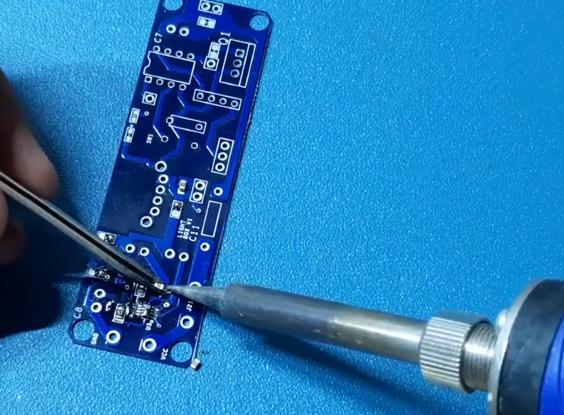
Now we have to solder the PCB in order to go to the next step so for this obtain a soldering iron and solder it .
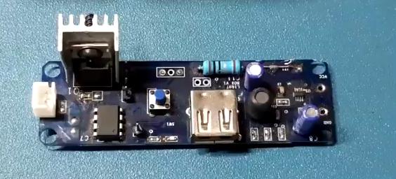
Now what you have done that should look like the below picture and your circuit is now ready for testing phase.
The working principle of the Above circuit
If we look properly to the circuit we can see that there is A small portion of the circuit to the right of the USB port the circuit is nothing but a voltage converter circuit which converts the 12V supply to the 5V for using in various applications and from the USB another microcontroller board can be connected for further requirements.
The portion on the left side of the USB is for the MOSFET circuit which gets powered upon getting power from the right side’s circuit and now you can test your LED by connecting to the left-most side’s connection pin and by pushing the middle button the brightness can be controlled.
Conclusion
So we have discussed the various MOSFETs that can be used in various circuit applications.