Learn to make a biometric-based attendance management system that takes the user’s thumbimpression to mark attendance!
It is widely accepted that a proper attendance management system is crucial for any kind of institution. Since there are a lot of practical issues involved in paper-based manual attendance methods, nowadays almost all companies have automated their process of attendance management.
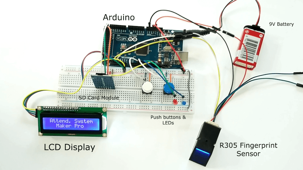
Throughout the article, I will show you how to build your own attendance management system using Arduino, fingerprint sensor & SD card module. This project can be the best choice for the final year project if you are an engineering student.
And it is surprisingly easy to build this in less time for an affordable budget. Moreover, this will be a very useful product that we can use in our daily life.
Let’s take a look at the components needed.
Required Components
- Arduino Uno/Mega
- R305/R307 Fingerprint Module
- 16x2 LCD with I2C Module
- 2 x Pushbuttons
- 2 x LEDs
- 2 x 10K Ohm Resistors
- Breadboard and Jumper Wires
Required Libraries
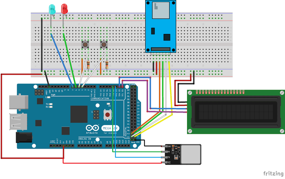
Wiring the Hardware
Even though the wiring diagram may look complex, it is quite simple to build.
To get user input, the fingerprint scanner interfaces directly with the Arduino. The LCD module and LEDs indicate the output or result. The SD card module saves the attendance report on an SD card. Two or more buttons can be used to control different processes.
Let’s go over how each module interfaces with the larger build to create our project.
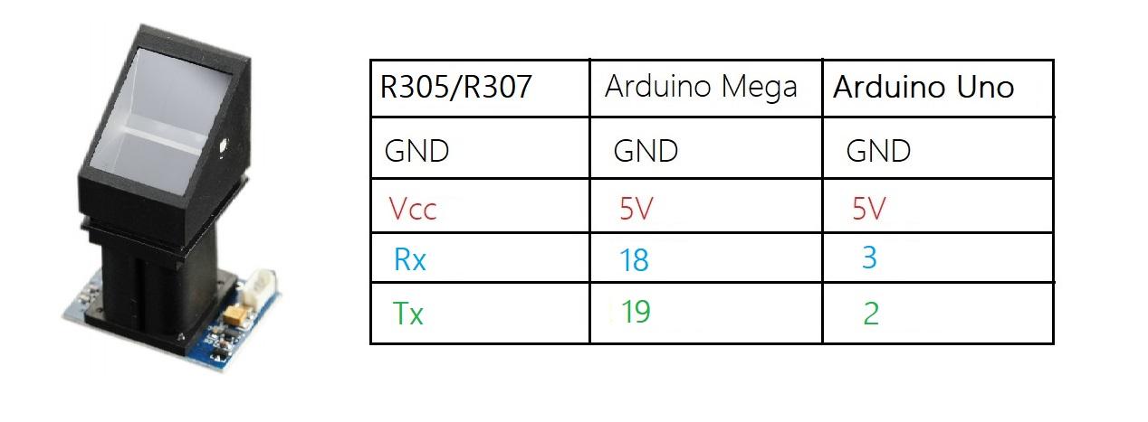
R305 Scanner to the Arduino
The R305/R307 fingerprint scanner has a TTL UART interface which can be directly connected to the Arduino UART.
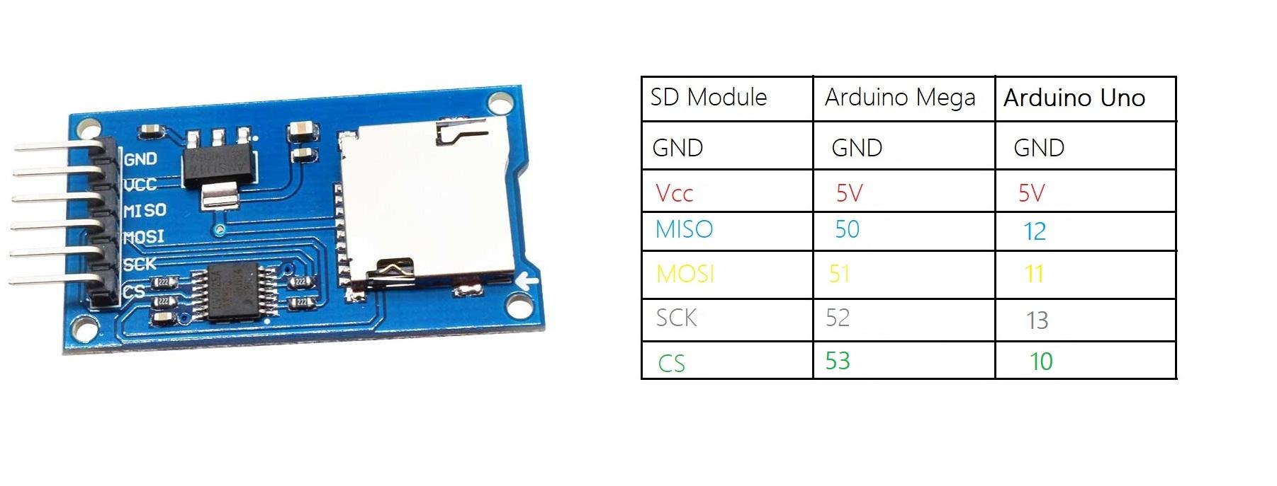
SD Card Module to the Arduino
The SD card module communicates with the Arduino over the serial peripheral interface (SPI) communication protocol. It can be simply connected to the Arduino’s hardware SPI pins.
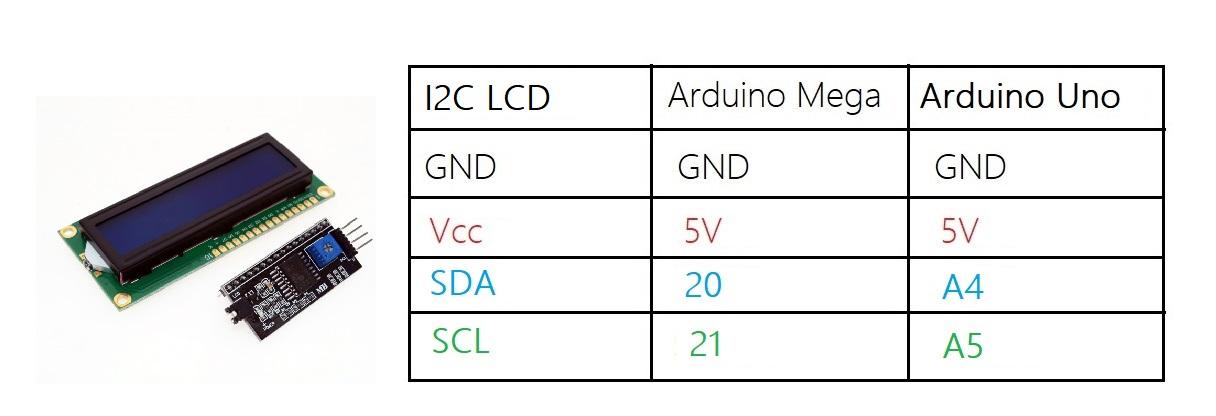
LCD with I2C Module to the Arduino
As the name implies, the LCD module communicates with Arduino through I2C communication.
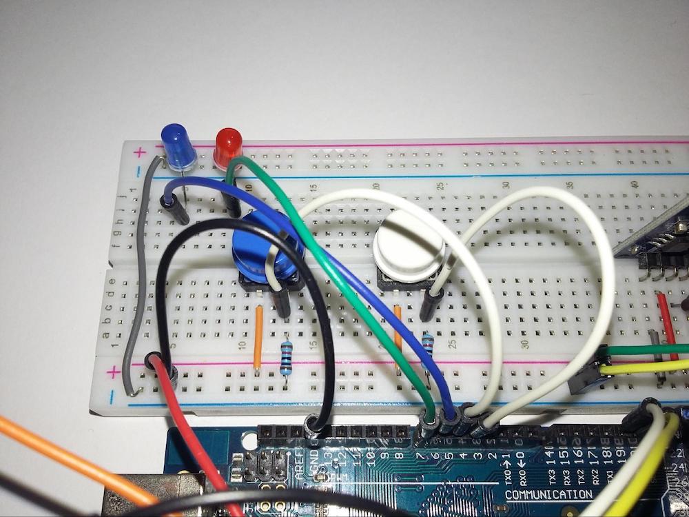
Finally, two LEDs and pushbuttons can be interfaced as shown in the image below.
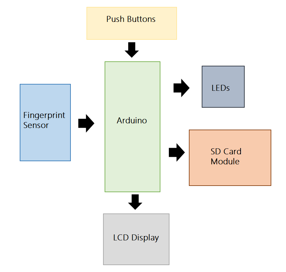
Fingerprint Scanner System Overview
The following block diagram shows the basic overview of the system.
The fingerprint sensor and pushbuttons act as input modules. Here, I am using two pushbuttons for the enrollment and identification processes. When we want to enroll a new user, the registration button must be pressed to start the registration process. After pressing the attendance button, the finger will be verified to mark attendance. The LCD modules and LEDs act as output modules. They will print messages and errors to give the visible output of the process.
Fingerprints save in the flash memory of the fingerprint sensor. The R305 module itself performs fingerprint collection, comparison, and search. The ID of the verified fingerprint is saved in a text file on the SD card. We can use that attendance report by removing the microSD card from the module.
Arduino Code
The Arduino code for this project is quite lengthy. You can find the full code at the following link:
Arduino Code for Fingerprint Attendance System
I will explain the code based on the two main processes:
- Fingerprint enrollment
- Fingerprint recognition and marking attendance
The Fingerprint Enrollment Process
All of the fingerprint sensor’s functions are controlled by the Adafruit fingerprint sensor library. The library contains the methods and functions to drive the fingerprint scanner.
Here, I created a function called getFingerprintEnroll() to enroll new fingerprints. Upon calling this function, the sensor receives two fingerprint scans (pictures of the fingerprint). Then the fingerprint image is saved by merging those two scans into one of the 256 entries in the built-in database. You will always receive an error message if the image is not captured correctly due to finger placement errors.
When storing the fingerprint, we have to decide the database position while considering the storage of the sensor.
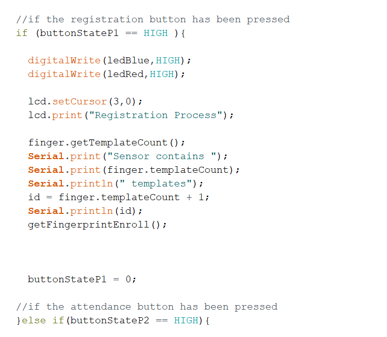
As you can see, we first have to find the number of fingerprints that are already stored in the sensor. We can get that number by using the getTemplateCount() function. Since storage position numbering starts from 0, set the ID by increasing the number by 1. The ID number is a global variable. So, the assigned ID number will be used in the getFingerprintEnroll() function when storing the fingerprint.
The Fingerprint Recognition and Marking Attendance Process
In the attendance marking process, the getFingerprintIDez() function is called. This function receives a user’s fingerprint and checks it with already stored fingerprints.
If the finger is not in the database, an error code is returned by the scanner. If the finger is matched, it will return the user ID number.
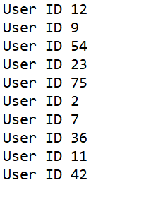
I have converted the ID numbers into a string variable to store them in the SD card. Finally, you will have an attendance report like this:
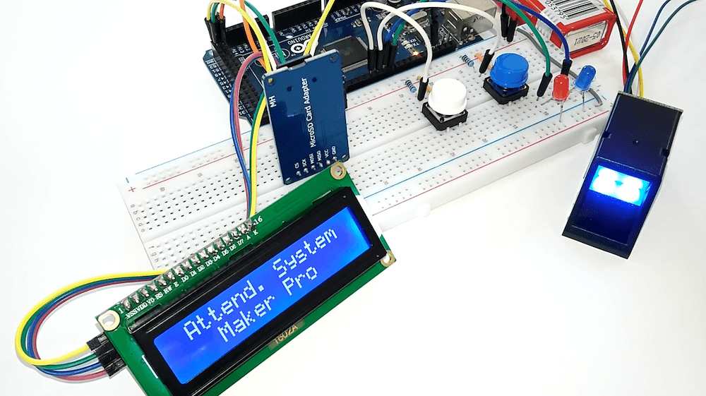
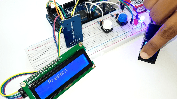
Demonstration of the System
Fingerprint Attendance System Demonstration
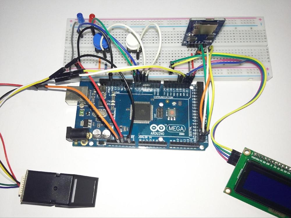
As you can see, the final product of this project can be built as a portable device. In the registration process, the user has to provide their fingerprint two times. That means each user has to take their finger away from the scanner and place it back on again in order to record.
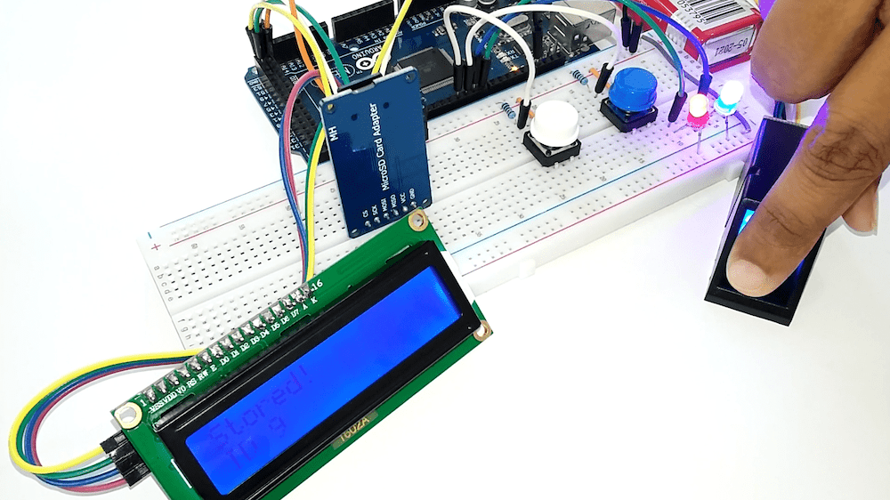
During the process of taking attendance, we need to press the start button (blue pushbutton) to start the process. The LCD display prompts the message “Place the Finger” to let us know the process has started. Then the user has to place their finger on the scanner to mark attendance. Once the fingerprint is matched, the message “Present” will prompt and the blue LED will turn ON. If there isn’t a match, the red LED will flash ON and the display shows the error message “Finger not Found.”
Further Reading and Information
Although this is a complete project, there is always room for improvement. Here are further improvements others have applied to this project.
- R305 has the capability to store up to 256 fingerprint templates in its memory. If your project needs more storage than this, there are some other alternatives, like the SparkFun GT521F52 fingerprint scanner.
- In this project, the attendance report is a text document with the user identification number. However, interfacing an RTC module will also give you the user’s arrival time.
- If you want an IoT solution for data storage, you can replace the Arduino board with an ESP32 or a Raspberry Pi and use cloud-based storage such as MySQL database.