Learn how you can use the machine learning program Wekinator to control servo motors with an Arduino UNO.
In this tutorial, we will learn how to control servo motors using machine learning techniques through the Wekinator platform. By inputting the necessary data for Wekinator to process, we can control the servo motors with Wekinator’s output.
Required Hardware and Software
Required Hardware
- Arduino UNO
- 2 servo motors
- breadboard
- jumper wires
Required Software
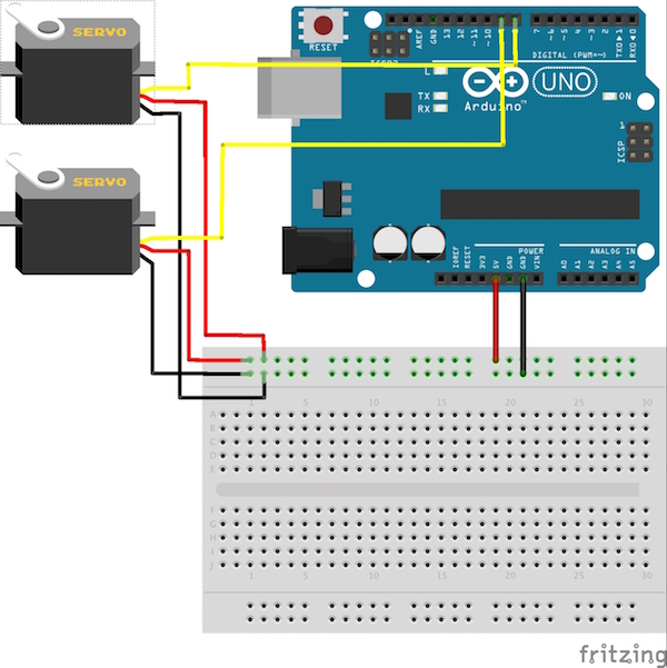
Circuit Diagram for Wekinator-Controlled Servo Motor
Start by connecting the red wires on each servo to the Arduino’s 5V pin. Then connect each servo’s black wire to the Arduino’s ground. Lastly, connect the yellow wire from one of the servos to pin 8 on the Arduino and the yellow wire from the other servo to pin 9.
Circuit diagram for controlling servos through Wekinator
How to Run Wekinator in Arduino IDE
Paste the Arduino-specific code provided at the end of this post into the Arduino’s IDE and upload it.
You will then need to download the sketch file from Wekinator’s Quick Walkthrough page.
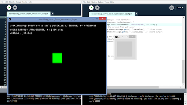
Download the on-screen mouse control examples found on the Walkthrough page. Unzip the file and run the sketch in processing. This sketch provides the input to Wekinator. You need another sketch for the output portion, which you’ll find at the end of this post. Paste that code into the processing window and run it—both processing output windows should look like this:
Processing output window in Wekinator
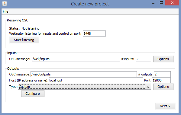
Open Wekinator and update the settings as follows:
- Set the input window to 2
- Set the and output window to 2
- Set the type to custom
Once your settings are updated, click configure.
Create new project window in Wekinator.
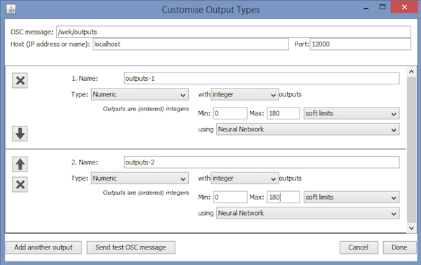
Once you click configure, the Customize Output Types window opens. In this window, adjust the settings as follows:
Customize Output Types window in Wekinator.
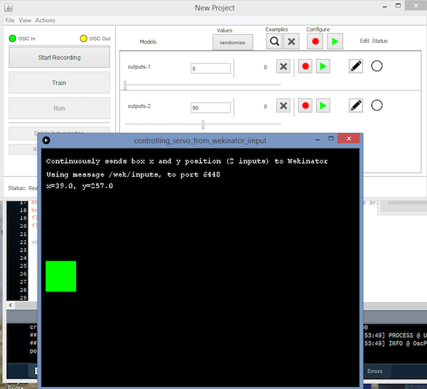
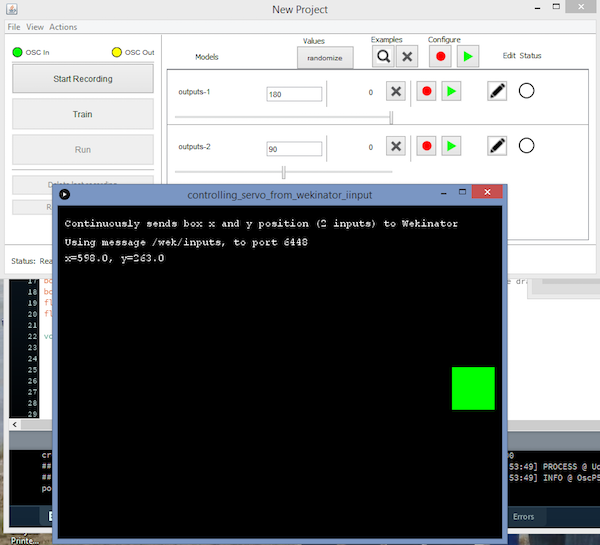
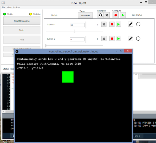
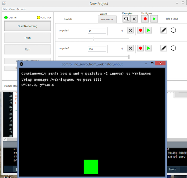
Drag the green box in the processing window to the center of left-hand side and adjust the settings in the Wekinator window to the values displayed below, then briefly start and stop the recording.
Move the green box in the processing window to the center of the right-hand side of the screen and adjust the settings in the Wekinator window as shown below. Once again, briefly start and stop the recording
Next, drag the green box in the processing window to the center top area of the window and adjust the settings to the ones shown in the Wekinator window below. Again, quickly start and stop the recording.
Finally, drag the green box in the processing window to the bottom center of the window and adjust the settings to reflect those displayed in the Wekinator window. For the last time, quickly start and stop the recording.
Click on the Train button, then select Run. When you drag the green box in the processing window, the servos connected to the Arduino will move accordingly.
Processing Code (Output From Wekinator)
import vsync.*; // Importing the library that will help us in sending and receiving the values from the Arduino
import processing.serial.*;  // Importing the serial library

// Below libraries will connect and send, receive the values from Wekinator
import oscP5.*;
import netP5.*;

// Creating the instances
OscP5 oscP5;
NetAddress dest;
ValueSender sender;

// These variables will be synchronized with the Arduino and they should be same on the Arduino side.
public int output;
public int output1;


void setup()
{
  // Starting the serial communication, the baudrate and the com port should be same as on the Arduino side.
  Serial serial = new Serial(this, "COM10", 19200);
  sender = new ValueSender(this, serial);

  // Synchronizing the variables as on the Arduino side. The order should be same.
  sender.observe("output");
  sender.observe("output1");

  // Starting the communication with Wekinator. listen on port 12000, return messages on port 6448
  oscP5 = new OscP5(this, 12000);
  dest = new NetAddress("127.0.0.1", 6448);
}

// Recieve OSC messages from Wekinator
void oscEvent(OscMessage theOscMessage) {
  if (theOscMessage.checkAddrPattern("/wek/outputs") == true) {
    // Receiving the output from Wekinator
    float value = theOscMessage.get(0).floatValue(); // First output
    float val = theOscMessage.get(1).floatValue();  // Second output

    // Converting the output to int type
      output = int(value);
      output1 = int(val);
  }
}

void draw()
{
  //  Nothing to be drawn for this example
}
Arduino Code for Wekinator-Controlled Servos
#include <VSync.h>    // Including the library that will help us in receiving and sending the values from processing
#include <Servo.h>    // Including the servo library
ValueReceiver<2> receiver;  /*Creating the receiver that will receive up to 2 values.
Put the number of values to synchronize in the brackets */

/* The below two variables will be synchronized in the processing
and they should be same on both sides. */
int output;
int output1;

// Creating the instances
Servo myservo;
Servo myservo1;

void setup()
{
  /* Starting the serial communication because we are communicating with the
  Arduino through serial. The baudrate should be same as on the processing side. */
  Serial.begin(19200);

  // Initializing the servo pins
  myservo.attach(8);
  myservo1.attach(9);

  // Synchronizing the variables with the processing. The variables must be int type.
  receiver.observe(output);
  receiver.observe(output1);
}

void loop()
{
 // Receiving the output from the processing.
  receiver.sync();

  // Check for the info we're looking for from Processing
  if (output < 180) {
    myservo.write(output);
  }

  if (output1 <180)
  {
    myservo1.write(output1);
  }
}