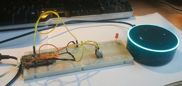
Learn how to set up an LED light or a 5V relay and control it using an Amazon Alexa Echo and ESP8266.
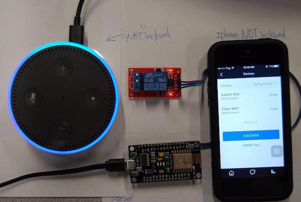
In this article, I will show how to set up an LED light or a 5V relay and control it using an Amazon Alexa Echo and ESP8266. If you already use Amazon Echo or Echo Dot at home or in your office, you can easily add your own devices. This tutorial inspired me to create this project. Moreover, you can easily modify this code to add as many devices as you need for creating new controls as well.
I am also adding a physical button to ESP8266 so we can easily turn the devices off and on with the button.
Software Requirements
For this project, you will need the following programs:
In addition to ESP8266 board support (NodeMCU), you should also install the following Arduino libraries (search in library manager or manually place the folder in Arduino/libraries):
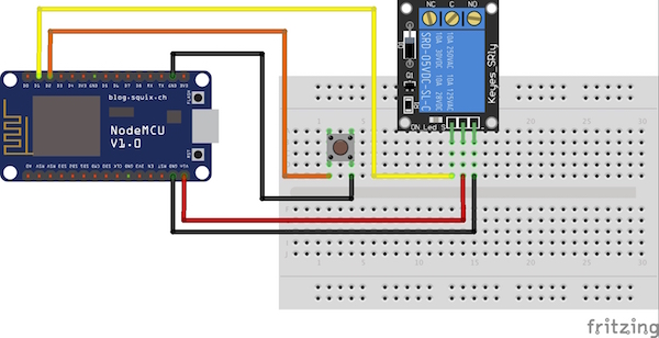
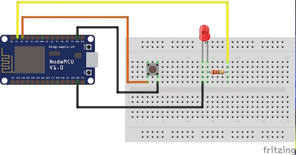
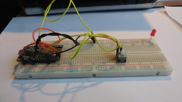
Connections and Schematic
ESP8266
- D1 → LED/relay
- D2→Push button
Programming the Arduino
The Arduino code for this project uses the example sketch for the fauxmoESP library, which emulates a Belkin WeMo device. Consequently, configuring your home automation switch follows exactly the same process for a commercial device, which is a breeze in the Alexa app. To discover the device, I've named my device "the light".
PLEASE BE CAREFUL OF HIGH VOLTAGE: Unplug everything before figuring the wiring with the relay. To control the AC portion of the circuit, I'm using a 5V relay — just interrupt the 220V wire and plug the stripped ends into the Normally Open and Common screw terminals. *Remember, if you don't have much experience working with high voltages, find someone who does to supervise.
Arduino IDE Configuration
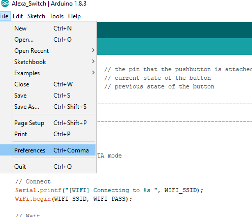
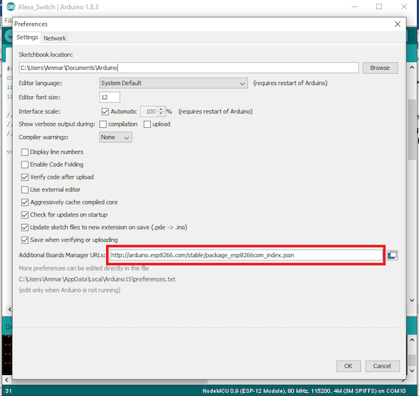
Click File -> Preferences
Next, install the board files and follow the mention steps.
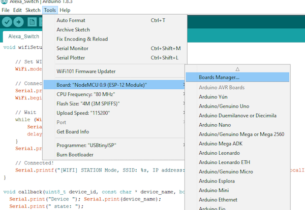
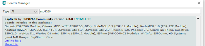
Tool→Board→ Board Manager
Search for ESP8266 and install the module package.
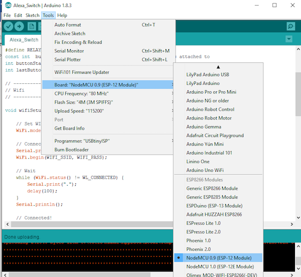
Select your board as shown in the figure below.
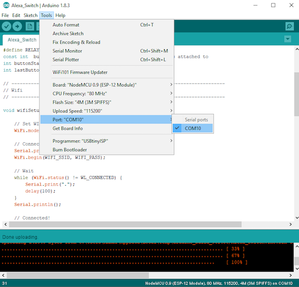
After this, select the board port.
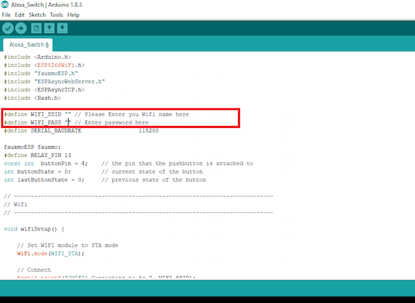
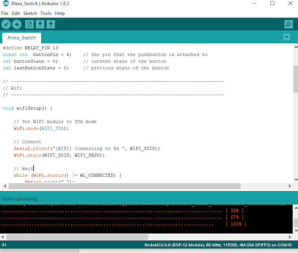
After the port selection, edit the source code and change the Wi-Fi name and password as shown in the figure:
Arduino Code
#include <Arduino.h>
#include <ESP8266WiFi.h>
#include "fauxmoESP.h"
#include "ESPAsyncWebServer.h"
#include <ESPAsyncTCP.h>
#include <Hash.h>

#define WIFI_SSID "" // Please Enter you Wifi name here
#define WIFI_PASS "" // Enter password here
#define SERIAL_BAUDRATE                 115200

fauxmoESP fauxmo;
#define RELAY_PIN 5
const int  buttonPin = 4;    // the pin that the pushbutton is attached to
int buttonState = 0;         // current state of the button
int lastButtonState = 0;     // previous state of the button

// -----------------------------------------------------------------------------
// Wifi
// -----------------------------------------------------------------------------

void wifiSetup() {

    // Set WIFI module to STA mode
    WiFi.mode(WIFI_STA);

    // Connect
    Serial.printf("[WIFI] Connecting to %s ", WIFI_SSID);
    WiFi.begin(WIFI_SSID, WIFI_PASS);

    // Wait
    while (WiFi.status() != WL_CONNECTED) {
        Serial.print(".");
        delay(100);
    }
    Serial.println();

    // Connected!
    Serial.printf("[WIFI] STATION Mode, SSID: %s, IP address: %s\n", WiFi.SSID().c_str(), WiFi.localIP().toString().c_str());
}

void callback(uint8_t device_id, const char * device_name, bool state) {
  Serial.print("Device "); Serial.print(device_name);
  Serial.print(" state: ");
  if (state) {
    Serial.println("ON");
    digitalWrite(RELAY_PIN, HIGH);
  } else {
    Serial.println("OFF");
    digitalWrite(RELAY_PIN, LOW);
  }
}

void setup() {
    pinMode(RELAY_PIN, OUTPUT);
    pinMode(buttonPin, INPUT_PULLUP);
    digitalWrite(RELAY_PIN, LOW);
    // Init serial port and clean garbage
    Serial.begin(SERIAL_BAUDRATE);
    Serial.println("FauxMo demo sketch");
    Serial.println("After connection, ask Alexa/Echo to 'turn <devicename> on' or 'off'");

    // Wifi
    wifiSetup();

    // Fauxmo
    fauxmo.addDevice("the light");
    fauxmo.onMessage(callback);
}

void loop() {
  fauxmo.handle();

  // read the pushbutton input pin:
  buttonState = digitalRead(buttonPin);

  // compare the buttonState to its previous state
  if (buttonState != lastButtonState) {
    // if the state has changed, increment the counter
    if (buttonState == LOW) {
      Serial.println("on");
      digitalWrite(RELAY_PIN, HIGH);
    }
    else {
      // if the current state is LOW then the button
      // went from on to off:
      Serial.println("off");
      digitalWrite(RELAY_PIN, LOW);
    }
    // Delay a little bit to avoid bouncing
    delay(50);
  }
  // save the current state as the last state,
  //for next time through the loop
  lastButtonState = buttonState;
}
Now it's Time to Play!
Ask your Alexa to discover the new device after uploading the code and it will detect your smart home device, which is the ESP8266. Control it by saying, “Alexa Turn On/Off light”. The Alexa in this case can either be your computer or the Amazon Echo.