Learn how to automate your home using the YK04 RF module with a remote control connected to an Arduino UNO.
As technology changes, its effect on human daily life is becoming increasingly lithe—especially in controlling household appliances.
Electrical installations are at the heart of every building, so intelligent building control increases safe and effective control, ultimately saving energy and manpower. Home automation systems perform lighting control and regulation, conditioning heating, equipment ventilation and air conditioning equipment, load and energy management, audio and video systems, security and monitoring, human-machine interface, and more.
In today’s context of Wi-Fi and Bluetooth connected systems, it’s convenient to have a completely standalone RF-based control solution that is more robust and stable and independent from glitchy Wi-Fi or a phone’s battery life.
This project is for those who want to have an old-school stand-alone RF control system for controlling things in their home.
RF-Based Home Automation System
Installing a home automation system with an RF-controlled remote control also opens up opportunities to make your house more intelligent. Smart homes are progressively flowing from customary switches to centralized control systems that utilize RF control switches.
Currently, traditional wall switches located in different parts of the house make it difficult for people to approach them. To accomplish this, an RF remote controller is connected to the TX side of the microcontroller, which sends commands to the receiver to connect different loads together. By operating a specific remote switch on the TX, the load can be turned on/off remotely via wireless technology.
The circuit uses a radio module to make a wireless remote control that can be used to drive o / p from a distance. As the name implies, the RF module uses RF signals to send signals at a specific frequency and baud rate.
How the RF Remote Control Works
This project involves a 4-channel RF remote home automation system that can be used by a family. You can use this system to control any of your home appliances. You can control things such as LED light bulbs, fans, cell phone chargers, your refrigerator, and more.
We will be using a 315 MHz RF module and remote with a maximum range of up to 50 meters in this system.
Required Hardware
- Arduino UNO
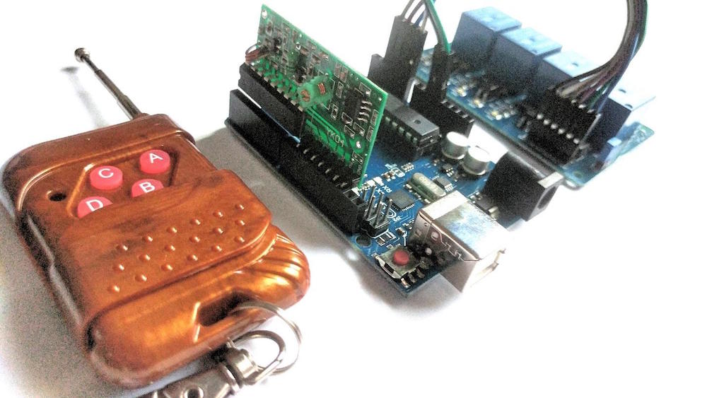
- RF Module YK04 with remote
- 4 channel relay
Circuit Diagram
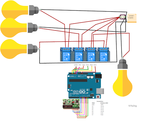
Always make sure that proper precautions are taken when you are working with high voltage AC power sources. Make sure they are well isolated from your DC boards and double check the connections going to the relays. Make the connections as per the Fritzing diagram below:
Home automation Fritzing diagram.
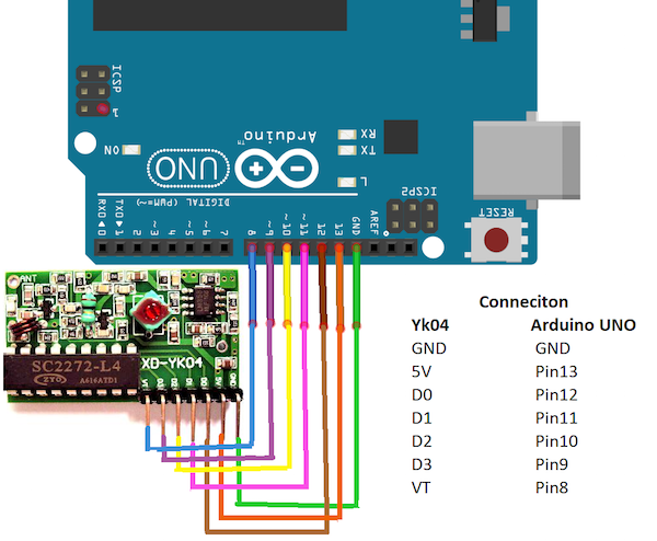
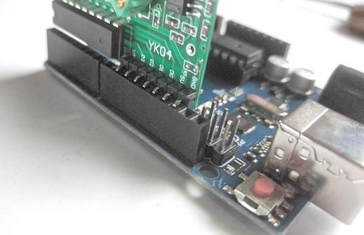
A closeup of the connections between the Arduino UNO and the RF module.
Relay Module to Arduino UNO Connections
- VCC to 5V
- IN1 to A0
- IN2 to A1
- IN3 to A2
- IN4 to A3
- GND to GND
Yk04 to Arduino UNO
- GND to GND
- 5V to 13
- D0 to 12
- D1 to 11
- D2 to 10
- D3 to 9
- VT to 8
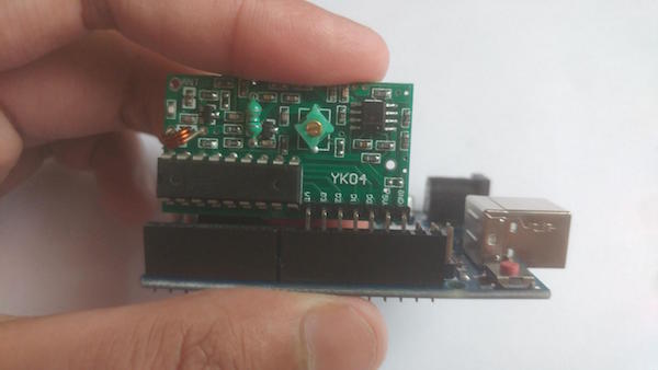
The Yk04 module connected to the Arduino UNO front view.
The Yk04 module connected to the Arduino UNO rear view.
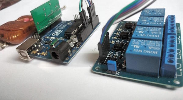
The Arduino UNO, YK04, and 4-channel relay properly connected.
Required Software
Project Source Code
Copy the source code below to the Arduino IDE and after checking your connections again, upload the code.
/*
 4 push signal and one relay module 4 relay with Remote

 Turns on and off 4 relays connected to digital
*/
// Read RF remote button codes using the RM4 library and send them over serial.
#include <rm4.h>

// Arduino pin connected to the receiver VCC in. Set this high to enable the
// receiver.
static const int kEnablePin = 13;

// Arduino pins connected to the data pins on the receiver.
static const int kData0Pin = 9;
static const int kData1Pin = 10;
static const int kData2Pin = 11;
static const int kData3Pin = 12;
const int relay1 =  14;             // the number of the relay1 pin
const int relay2 =  15;             // the number of the relay1 pin
const int relay3 =  16;             // the number of the relay1 pin
const int relay4 =  17;             // the number of the relay1 pin

// Create an RM4 object to read the button codes from the remote.
RM4 remote(kData0Pin, kData1Pin, kData2Pin, kData3Pin);

void setup() {
  // Initialize the serial interface.
  Serial.begin(9600);

  // Turn on the receiver.
  pinMode(kEnablePin, OUTPUT);
  digitalWrite(kEnablePin, HIGH);
  pinMode(relay1, OUTPUT);
  pinMode(relay2, OUTPUT);
  pinMode(relay3, OUTPUT);
  pinMode(relay4, OUTPUT);

}

void loop() {
  // Print the button code to the serial interface every 100 ms.
  const int button_code = remote.buttonCode();
   if (button_code == 8) {                      // pin 2 is pressed and connected to GND so it will be LOW
    digitalWrite(relay1, LOW);                    // remove 5v from pin 11 so relay in1 will be 0v and this make relay on
    delay (2000);                                 // wait 1 second
  } else {
    digitalWrite(relay1, HIGH);                   // add 5v to arduino pin 11 so relay in1 will be 5v and this make relay off
  }
   if (button_code == 2) {                      // pin 2 is pressed and connected to GND so it will be LOW
    digitalWrite(relay2, LOW);                    // remove 5v from pin 11 so relay in1 will be 0v and this make relay on
    delay (2000);                                 // wait 1 second
  } else {
    digitalWrite(relay2, HIGH);                   // add 5v to arduino pin 11 so relay in1 will be 5v and this make relay off
  }
   if (button_code == 1) {                      // pin 2 is pressed and connected to GND so it will be LOW
    digitalWrite(relay3, LOW);                    // remove 5v from pin 11 so relay in1 will be 0v and this make relay on
    delay (2000);                                 // wait 1 second
  } else {
    digitalWrite(relay3, HIGH);                   // add 5v to arduino pin 11 so relay in1 will be 5v and this make relay off
  }
   if (button_code == 4) {                      // pin 2 is pressed and connected to GND so it will be LOW
    digitalWrite(relay4, LOW);                    // remove 5v from pin 11 so relay in1 will be 0v and this make relay on
    delay (2000);                                 // wait 1 second
  } else {
    digitalWrite(relay4, HIGH);                   // add 5v to arduino pin 11 so relay in1 will be 5v and this make relay off
  }

 // Serial.println(button_code);

 // delay(100);
}
Complete RF Remote Control Project
Once you have uploaded this code you should be able to have functionality similar to the video below.