Learn to build a simple FM Radio using SparkFun FM Tuner and Arduino Uno to receive and display broadcast information.
In a previous article, we took a look at FM radios and the parts we can use to build a simple FM radio from scratch. This project serves as an introduction to incorporating an FM radio receiver that is also capable of receiving information about the broadcast into your projects.
We will be using a SparkFun breakout board for the Silicon Laboratories Si4703, along with an Arduino Uno, and a powered speaker to create a simple FM radio that can seek a radio station, adjust the volume, save favorite stations, and, of course, play audio.
The Arduino Uno will interface with a computer via serial communication to allow control over the system and feedback to the user. Plus, the system will be able to receive and display information from the broadcaster that is embedded in subcarrier frequencies.
Now, let’s take a look at the build.
Solder Headers to the Si4703 Breakout
The SparkFun Si4703 FM Tuner Basic Breakout comes without headers attached, which is the way almost every SparkFun breakout board ships. This allows you the flexibility to incorporate the Si4703 breakout board into your project using whatever kind of connections you need.
You can solder wires directly to the pins on the breakout board, you can connect the breakout board to another PCB, or you can solder on male or female headers. In this project, because I will be assembling the circuit on a solderless breadboard, I will be using male headers. If you are not using a breadboard, however, you may wish to use female headers instead.
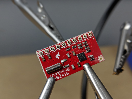
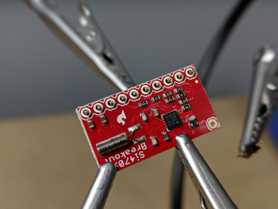
The Si4703 Breakout Board
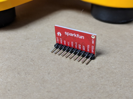
Soldering male headers onto the board allows it to plug into a solderless breadboard.
Wiring
To begin building the project, we will wire the SparkFun Si4703 breakout to the Arduino Uno and to the speaker. You can wire everything together directly, as discussed in the previous section, or assemble the electronics on the solderless breadboard.
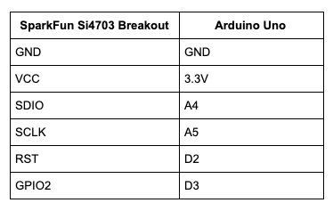
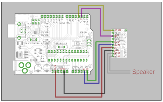
The wiring diagram and table below shows all the connections needed to make the project function. After the wiring diagram, more information is provided about the electronics design and the different connections.
Circuit diagram of our connections between the Arduino UNO and Si4703.
Power
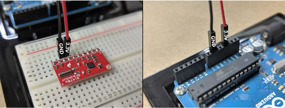
First, we will wire the power and ground connections to the SparkFun Si4703 FM Tuner Basic Breakout.
**Note that the Si4703 runs on 3.3V, not 5V.
Connect the Arduino 3.3V pin to the VCC pin on the Si4703 breakout. Then, connect one of the Arduino GND pins to the Si4703 GND pin.
Power and ground connections to the SparkFun Si4703 FM Tuner Basic Breakout.
Data Connections
The SparkFun FM Tuner Basic Breakout and the Arduino Uno communicate over four wires. The GPIO2 connection allows the Arduino Uno to select among different device modes like seek/tune, and RDS functions.
In this tutorial, we will be using a two-wire interface to control the Si4703. Those two wires are the SDIO and SCLK pins, connected to A4 and A5 respectively. Finally, the RST pin is used to enable and disable the Si4703. When D2 is set to LOW, the Si4703 is disabled, and when it is set to HIGH, the Si4703 is brought out of reset mode.
SparkFun FM Tuner Basic Breakout and the Arduino Uno data connections.
Speaker Connection
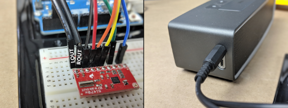
The final two connections are the audio connections between the Si4703 breakout board and the powered speaker.
For the purposes of this project, it does not matter which side of the 3.5mm connector the left and right audio channels connect. Simply plug the 3.5mm pigtail connector into the Lout and Rout pins on the FM Tuner Breakout board.
Audio connections between the breakout board and the powered speaker.
Code
Now that the electronics are assembled, the next step is to upload code to the Arduino. There are two steps involved:
- Install the Si4703 library
- Upload the Si4703_test sketch to the Arduino Uno
Installing the Library
To make controlling the SparkFun FM Tuner Basic Breakout easier and the project code cleaner, we will use a library with functions for controlling the Si4703.
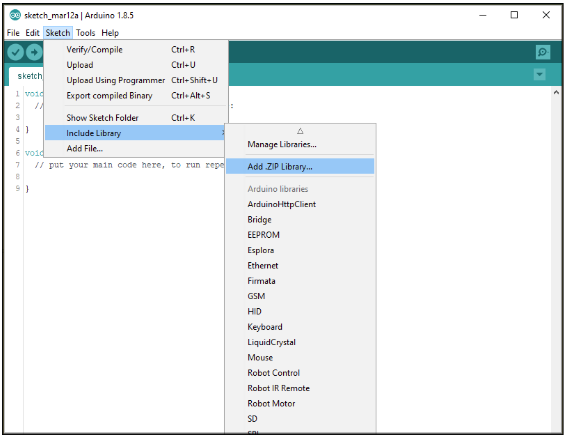
First download the library .zip folder and save it somewhere on your computer where you will be able to find it later. Then, open the Arduino IDE. In the Arduino IDE, from the menu, select Sketch > Include Library > Add .ZIP Library….
Then, navigate to the location in which you stored the Si4703 library and select the .zip file. When the library installation is successful, you will get a confirmation at the bottom of the window.
Uploading the Code
Now that the Si4703 library has been installed into the Arduino development environment, we can program the Arduino Uno with the code that will run our simple FM radio. First, download the sketch and open it in the Arduino IDE.
// Arduino Uno Basic FM Radio using SparkFun Si4703 Breakout
// Author:  Scott Hatfield (aka Toglefritz)
// Published on Maker Pro

/*
DESCRIPTION:
  This sketch for the Arduino Uno controls a simple FM radio using an Si4703 radio
  receiver. The sketch allows control of the system and feedback to the user over
  serial. The system can seek radio stations, store three favorited radio stations,
  adjust volume, and print RDS information.

LICENSE:
  This code is licensed under a Creative Commons Attribution-NonCommercial-ShareAlike 4.0 International License.
  < https://creativecommons.org/licenses/by-nc-sa/4.0/ >

PARTS:
  * Arduino Uno R3: < https://www.sparkfun.com/products/11021 >
  * SparkFun FM Tuner Basic Breakout:  < https://www.sparkfun.com/products/11083 >
  * Generic powered speaker

HARDWARE CONNECTIONS:
  * Si4703 VCC --> 3.3V
  * Si4703 GND --> GND
  * Si4703 SDIO --> A4
  * Si4703 SCLK --> A5
  * Si4703 RST --> D2
  * Si4703 GPIO2 --> D3
  * Si4703 ROUT --> Speaker
  * Si4703 LOUT --> Speaker
*/

#include <Si4703_Breakout.h>    // Load the SparkFun Si4703 library < https://cdn.sparkfun.com/assets/learn_tutorials/2/7/4/Si4703_Breakout.zip >
#include <Wire.h>

int resetPin = 2;   // The Si4703 breakout RST pin connects to the Arduino D2 pin
int SDIO = A4;    // The Si4703 breakout SDIO pin connects to the Arduino A4 pin
int SCLK = A5;    // The Si4703 breakout SCLK pin connects to the Arduino A5 pin

// Initialize the Si4703_Breakout object
Si4703_Breakout radio(resetPin, SDIO, SCLK);
int channel;
int volume = 5;
char rdsBuffer[10];

// Favorite stations
int favA = 1041;    // Set your favorite stations by inputting their FM frequency (omitting the period)
int favB = 931;
int favC = 937;

void setup()
{
  // The Arduino communicates with the computer via serial
  Serial.begin(9600);
  Serial.println("\n\nSi4703_Breakout Basic Radio");
  Serial.println("\n\nControls:");
  Serial.println("a, b, c     Favourite stations");    // In the configuration above, you can set three favorite stations
  Serial.println("+, -     Volume (max 15)");
  Serial.println("u, d     Seek up / down");
  Serial.println("r,       Print RDS Data (15 sec timeout)");
  Serial.println("\n\n");

  radio.powerOn();    // Enable the Si4703
  radio.setVolume(5);    // Set the starting volume to 5 (out of 15)
}

void loop()
{
  // Listen for serial commands
  if (Serial.available())
  {
    char ch = Serial.read();

    // u = seek up
    if (ch == 'u')
    {
      channel = radio.seekUp();
      displayInfo();
    }

    // d = seek down
    else if (ch == 'd')
    {
      channel = radio.seekDown();
      displayInfo();
    }

    // + = increase volume
    else if (ch == '+')
    {
      volume ++;
      if (volume == 16) volume = 15;
      radio.setVolume(volume);
      displayInfo();
    }

     // - = decrease volume
    else if (ch == '-')
    {
      volume --;
      if (volume < 0) volume = 0;
      radio.setVolume(volume);
      displayInfo();
    }

    // a = favorite station a
    else if (ch == 'a')
    {
      channel = favA;
      radio.setChannel(channel);
      displayInfo();
    }

    // b = favorite station b
    else if (ch == 'b')
    {
      channel = favB;
      radio.setChannel(channel);
      displayInfo();
    }

    // c = favorite station c
    else if (ch == 'c')
    {
      channel = favC;
      radio.setChannel(channel);
      displayInfo();
    }

    // r = print RDS information
    else if (ch == 'r')
    {
      Serial.println("RDS listening...");
      radio.readRDS(rdsBuffer, 15000);
      Serial.print("RDS info: ");
      Serial.println(rdsBuffer);
    }
  }
}

// The displayInfo function prints the current channel and volume over serial
void displayInfo()
{
   Serial.print("Channel:");
   Serial.print(channel);
   Serial.print(" Volume:");
   Serial.println(volume);
}
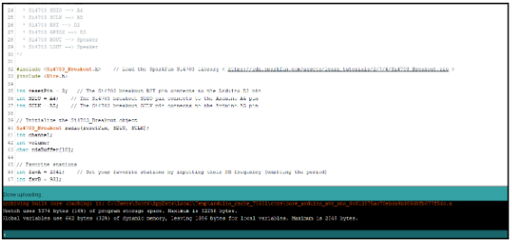
The code can be uploaded to the Arduino Uno over USB just like any other sketch.
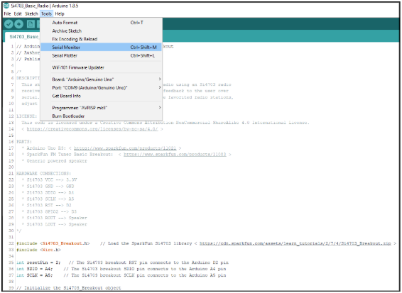
The code will interface your computer using serial communication. Therefore, after the code successfully uploads to the Arduino Uno, we will need to open and set up the Serial Monitor. You will find the Serial Monitor tool in Tools > Serial Monitor.
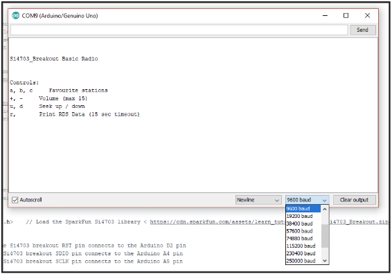
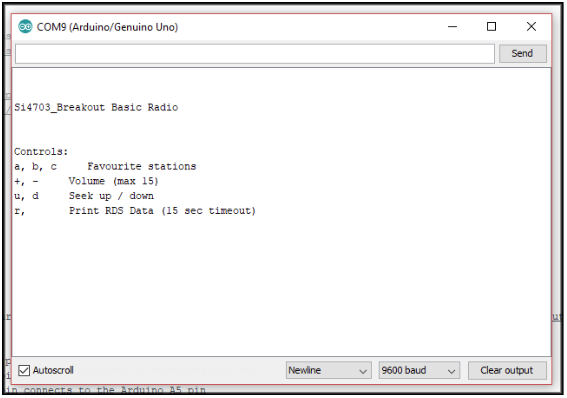
With the Serial Monitor open, make sure the baud rate is set to 9600 using the drop-down in the lower-right corner of the window. When the sketch starts running, you should see a message from the Arduino with instructions for controlling the radio.
Project Videos
Check out the videos below to see the project take shape!
Controlling the Radio
The Arduino Uno communicates with the computer over serial in order to receive commands and to send feedback. When the sketch first starts running, the Arduino will print instructions to the Serial Monitor with the various commands used to control the system.
Connecting the Optional Antenna
If you find that the system is having a hard time picking up radio stations, you can bolster the performance of the Si4703 by connecting an antenna to the ANT pin on the breakout board. The antenna is not absolutely necessary if the stations you wish to listen to have a strong signal in your area. However, the antenna is useful for picking up more distant signals.
The antenna is made from a single length of wire. The wire can be soldered onto the ANT pin on the FM Tuner Basic Breakout, or it can be attached with an alligator clip. With the antenna connected, you should be able to pick up radio signals more easily.
Other Radio Projects
